Chapter/Index: Introduction | A | B | C | D | E | F | G | H | I | J | K | L | M | N | O | P | Q | R | S | T | U | V | W | X | Y | Z | Appendix
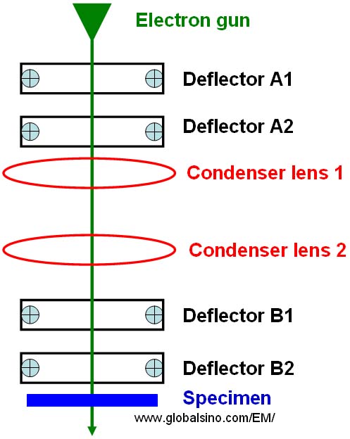
| A deflector for electron-beam deflection in EMs has been applied to align, tilt, shift, scan the electron beam, and so on. The deflector, usually including a pair of deflection coils, is called the double-deflection system. Figure 1920a shows the schematic illustration of deflectors and condenser lenses above the specimen in TEM. The electron gun consists of a filament and a column where the incident electrons are accelerated. The functions of double deflectors A1 and A2 are gun shift and tilt, while the functions of double deflectors B1 and B2 below the condenser lens 2 and above the specimen are beam shift and tilt as well as tilt for dark field imaging. The beam shift and tilt are also called illumination shift and tilt.
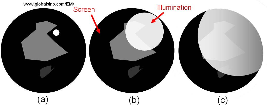
In TEM operation, the electron beam at near crossover should be centered using the condenser X Y deflection coils (B1 and B2 in Figure 1920a) because an unevenly illuminated field of view will be induced when it is opened up if the beam is off center as shown in Figure 1920b.
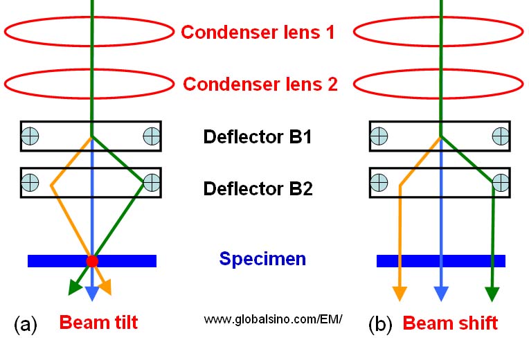
As shown in Figure 1920c, the double deflectors B1 and B2 are normally applied to either shifting or tilting the electron beam. The deflectors work in opposite senses in both cases, but the strength ratios of the two deflectors B1 and B2 are different for the shift and tilt operations. Furthermore, it is necessary to note that there are different pairs of deflectors for the two Cartesian co-ordinates (x and y).
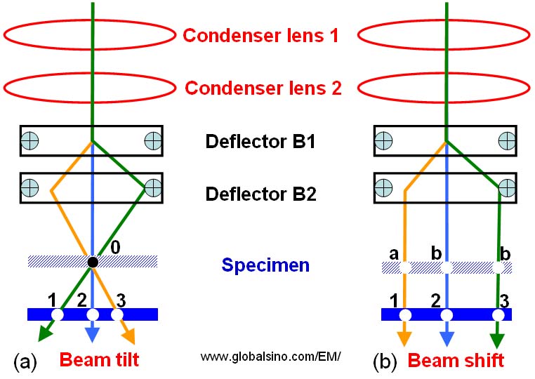
If the specimen is at a different height, for instance, it is not at Eucentric height, the beam-illuminating location is not affected by beam shift as shown in Figure 1920d (b), but it is clearly affected by beam tilt as shown in Figure 1920d (a). In order to eliminate this effect in the tilting case, we have to re-adjust the strength ratios of the two deflectors B1 and B2.
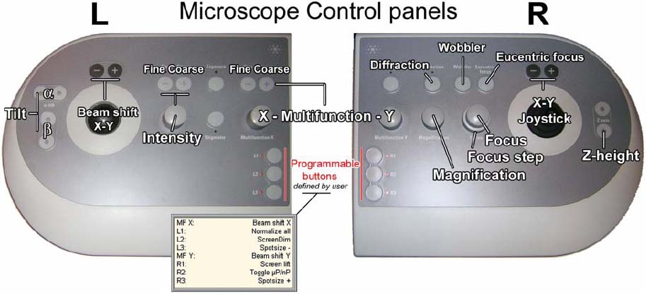
Therefore, by optimizing the deflector balance, the operator can tilt the electron beam only (or shift the beam only), independent of the beam shift operation (or the beam tilt operation). These “pure” operations are sometimes called tilt purity (balance) and shift purity (balance). Ideally, the electron beam tilt function should just rotate the beam through a point in the specimen, for instance, when the specimen is at the shadowed location in Figure 1920d. This point is called pivot point or rocking point. However, the pivot point is controlled by both the strength ratios of the two deflectors B1 and B2 and the specimen height. Therefore, if the specimen height is changed, the pivot point should be re-adjusted with the compensation of the strength ratios. Note that the pivot point can be re-adjusted when the beam is scanned through all tilt-angles. In some modern TEMs, the pivot point can be easily obtained by clicking a button called ‘pivot points’ which leads the beam jump between two tilt settings. If the pivot point is incorrect, the two beams are separated laterally and two knobs (e.g. called multifunction in FEI systems shown in Figure 1920e) are simply adjusted until the two beams are coincident on the phosphor screen. Again, these knobs adjust the strength ratios of deflectors B1 and B2 in both x and y directions. It is important to first have the pivot-point aligned in both the x and y directions so that translating the beam does not introduce an obvious beam tilt, and so that applying a beam tilt does not cause an obvious beam translation.
Another operation example of shift and tilt balance alignment is in JEOL TEM systems (e.g. 2100F): In caustic image theory, a coma-free condition means that the projection of the direct electron beam lies in the center of the caustic curve. Therefore, coma aberration can be corrected by centering the direct beam [1]. This beam centering can be done by bringing the direct electron beam to the center of caustic curve using the beam tilt controls.
[1] K. Kimoto, K. Ishizuka, N. Tanaka, Y. Matsui, Ultramicroscopy 96 (2003) 219.
|