=================================================================================
The achievable instrumental performance of a STEM is mainly determined by the size and shape of the incident electron probe. The most important optical factor in achieving the optimum probe profile is the radius of the probe-forming aperture, which determines the convergence semi-angle of the illumination. Small deviations from this optimum can degrade both the resolution and interpretability of the image contrast.
The objective aperture for STEM is the probe-forming aperture. However, this terminology can be confusing since in TEM/STEM microscopes this aperture is usually the same aperture used as the condenser aperture 2 (C2) for TEM operation. To avoid confusion the term probe-forming aperture is actually used in most applications and publications.
Figure 3600a shows the structure of the electron probe-forming system in STEM mode in JEOL JEM-2010F TEMs. The beam current decreases due to the probe-forming aperture.
Figure 3600a. Schematic illustration of the probe-forming electron optics in STEM mode in JEOL JEM-2010F TEMs.
Figure 3600b shows the schematic comparison between contrast transfer functions (CTFs) for a parallel-beam CTEM and a STEM. For TEM imaging, the higher frequencies should be excluded by a proper objective aperture marked by the red arrow because they introduce contrast reversals. The probe forming aperture in STEM is often compared to the objective aperture in parallel beam illumination in CTEM. The effect of aperture size on the CTF for HAADF STEM imaging is a much more complex issue. The point spread function is proportional to the square of the probe wavefunction and not the wavefunction itself (as in Bright field CTEM). The response to increasing the aperture size is non-linear and affects all spatial frequencies, not just the highest. The phase errors at large angles to the optic axis essentially are mixed in to the lower frequencies, degrading both contrast and image localization. For STEM imaging, a proper probe-forming aperture should be applied to match the need of the spatial frequency marked by the green arrow.
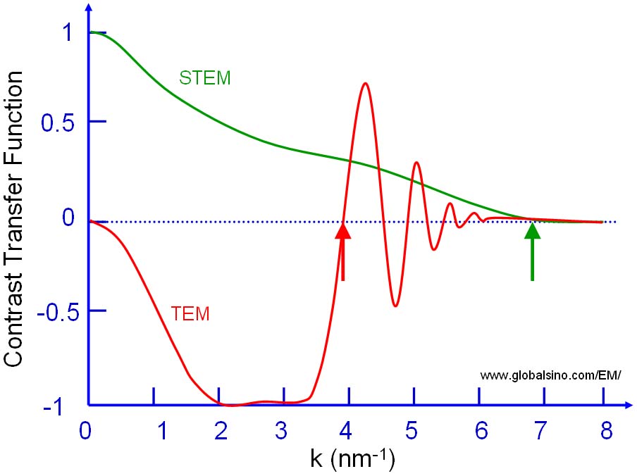
Figure 3600b. Schematic illustration of contrast transfer function (CTF) for: (a) A parallel-beam CTEM and (b) A STEM.
Figure 3600c shows a Ronchigram pattern taken at Gaussian focus from an amorphous thin film in TEM. The green circle marks the unaberrated part of Ronchigram that should be selected by objective aperture for STEM imaging.
Figure 3600c. Ronchigram pattern taken at Gaussian focus.
The intensity distribution in the STEM images depends on the illumination lens settings and the size of the STEM objective aperture. To form Z-contrast images, the STEM objective aperture must be inserted to cut out high-angle electron rays, and an annular detector must be inserted after the projector lens system.
In principle, the probe size should be independent of the dimension of the C2 aperture. However, in reality, the C2 aperture affects the probe size, as high convergence angles (> 10−2 rad) are normally used to form very small probes, resulting in wide tails in the probe that are cut off by the aperture.
|