|
|
Dipole Design for Cs Corrector in EMs
- Practical Electron Microscopy and Database -
- An Online Book -
|
|
https://www.globalsino.com/EM/
|
|
This book (Practical Electron Microscopy and Database) is a reference for TEM and SEM students, operators, engineers, technicians, managers, and researchers.
|
=================================================================================
Figure 3661 shows the schematic illustration of dipole design which can be used for spherical aberration (Cs) correction.  indicates the direction of the electron beam. The blue lines represent the magnetic field lines, while the red line represents the Lorentz force on the electrons. The function of a dipole is to shift the electron beam. indicates the direction of the electron beam. The blue lines represent the magnetic field lines, while the red line represents the Lorentz force on the electrons. The function of a dipole is to shift the electron beam.
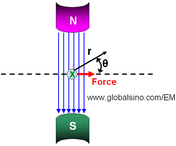
Figure 3661. Schematic illustration of dipole design which can
be used for spherical aberration (Cs) correction.
A EELS spectrometer consists of a couple of lenses. For instance, Enfina ER has 2 hexapoles and 5 electromagnetic round lenses, 7 dipoles for alignment, and 1 quadrupole and 1 additional hexapole for astigmatism correction.
|
=================================================================================
The book author (Dr. Liao) welcomes your comments, suggestions, and corrections, please click here for submission. You can click How to Cite This Book to cite this book. If you let Dr. Liao know once you have cited this book, the brief information of your publication will appear on the “Times Cited” page. This appearance can help advertise your publication.
|
|