=================================================================================
The quality of the TEM/STEM images is determined mainly by the performance of the objective lens as it usually has the largest product of field of view and the largest angle of any lens in the column. The objective lens consists of lens coils, a magnetic circuit (yoke), and a polepiece. The shape of the polepiece is the main factor determining the optical properties of the objective lens. The schematic illustration of JEM-2010F objective lens in Figure 3765a presents the typical objective lens in conventional TEMs. The specimen (for side-entry holder) is located at the center of the polepieces. Thee objective aperture (OA) is placed immediately below the specimen and the high contrast (HC) aperture goes through the lower polepiece.
Figure 3765a. Typical objective lens in conventional TEMs.
For an ideal objective lens, the incident electron probe simply forms an Airy disc in the back focal plane of the lens. This disc is the Fourier transform of the uniformly illuminated condenser aperture.
TEM images are focused with the objective lens. Variation in the field strength of the objective lens is the primary means of adjusting the focus of the images. Note that the image plane of the objective lens is also the first image plane
in the TEM system.
As shown in Figure 3765b, the objective lens is placed at the back of the specimen in TEM systems, while it is placed in front of the specimen in STEM systems. In the arrangement of the basic imaging systems of conventional transmission electron microscopy (CTEM), an electron beam emitted by a source radiates the TEM specimen, usually through an illuminating system of lenses as shown in blue in Figure 3765b. The incident electrons interact with the specimen and thus are scattered. The electron beam after interaction is then focused by the objective lens, forming an image. The image is further magnified by projector lenses to produce an image at proper magnifications. Note that in modern TEM systems additional lenses, intermediate lenses are also placed between objective lens and projector lenses.
For STEM, the same diagram can be used with a reversed direction of the electron beam also shown in Figure 3765b. The electron source for STEM replaces the TEM detection system (image plane). In modern STEM systems, a field-emission gun can be used to produce an electron source as small as 10 nm in diameter. One or more projector lenses in TEM (acting as condenser lenses in STEM) with a short focal length demagnify the source to provide the flexibility in the beam parameter. The beam is then demagnified further by the main lens in the systems, which is objective lens to form a small probe of 0.2 – 1 nm on the specimen. Therefore, a STEM probe can be considered as a demagnified image of the source. Note that the focal length of the objective lens can be as small as 1 mm. The scanning coils are deflector coils, built into the bore of the objective lens, and serve to scan the electron probe over the specimen. The detector on the STEM image plane collects the electrons transmitted, or scattered, by the specimen.
Figure 3765b. Schematic illustration of imaging geometries of TEM and STEM systems. The green lines show the common paths of the rays of CTEM and STEM illuminations. The blue arrows indicate the rays for the TEM illumination, while the red arrows indicate the directions of STEM rays. The STEM image is formed on the left-hand side, while the CTEM image is on the right-hand side. The yellow lenses are the common lenses for both STEM and CTEM systems.
About the objective lens, Figure 3765c (a) shows the principle of magnifying an image (Normal-Mag mode). A transmitted image of the specimen is first formed and magnified by the objective lens, and then is magnified further by two to four lenses, including an objective lens, intermediate lenses, and a projector lens. As shown in Figure 3765c (b), at extremely low magnification (e.g. used for survey of interest), the image is formed by the OM (objective-mini) lens, intermediate lenses, and projector lens. The Diff mode in Figure 3765c (c)presents an electron diffraction pattern. In the Normal-Mag mode, the focus of the 1st intermediate lens is adjusted to the image plane of the objective lens where a selected area aperture is located. However, in the Diff mode, the focus of the 1st intermediate lens is adjusted at the back focal plane of the objective lens. Table 3765 lists the status of the lenses and apertures in different operation modes.
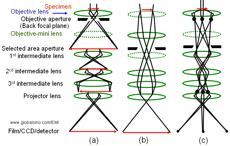
Figure 3765c. (a) Normal-Mag mode, (b) Low-Mag mode, and (c) Diff mode. The dashed-lenses are turned off in the relevant operation mode.
Table 3765. Status of the lenses and apertures in different operation modes*.
Lens |
|
|
|
|
On |
Off |
On |
Objective aperture (back focal plane)
|
Normally use |
Normally not use |
Normally not use |
|
Off |
On |
Off |
|
Normally not use |
Either use or not use |
Either use or not use |
Focus of 1st intermediate lens |
At the image plane of the objective lens |
- |
At the back focal plane of the objective lens |
|
On |
Off |
On |
|
On |
On |
On |
|
On |
On |
On |
|
On |
On |
On |
* "Normal-Mag mode" includes normal and high magnifications for HRTEM; "Low-Mag mode" includes very low magnifications, which is used for specimen survey; and "Diff mode" is for electron diffraction analysis. |
Like glass lenses in optical microscopes (EMs), all electromagnetic lenses suffer from defects such as astigmatism, chromatic and spherical aberrations, coma, and barrel or pincushion distortion. The first three are related to the objective lens. To minimize the aberrations, the objective lens has to be strong. On the other hand, from the operator's standpoint those three are the most important because of their influence on the resolution of the electron microscopes (EMs).
Objective lens in EMs normally uses a round magnetic lens. The strong magnetic flux is generated in a space between the upper and lower polepieces. The round magnetic lens cannot form a concave lens and thus, spherical aberration cannot be corrected by any combination of cylindrically symmetric round magnetic lenses. Note that the objective lens is the strongest lens in EMs and has the largest effect. In TEM systems, the first condenser and final projector lenses have short focal length and their designs are similar to that of the objective lens. However, the second condenser and the other projector lenses may be much weaker.
High-magnification CTEM imaging requires the first projector (P1) to run near its maximum strength, and the objective lens (OL) to project a focused image of the specimen into the front-focal plane of P1.
Astigmatism in condenser lens is important because it reduces the coherence of the electron beam, while astigmatism in objective lens is important because it induces a serious degradation of spatial resolution.
There are mainly two steps to correct the astigmatisms in TEMs:
i) Correct the astigmatisms of the diffraction (inter-mediate, IL) and condenser (CL) lenses. Before the astigmatism correction for objective lens (OL) , the IL and CL astigmatisms should be corrected. The CL astigmatism must especially be corrected (without objective aperture) to ensure the proper correction of the OL astigmatism.
ii) Correct the OL astigmatism.
In order to optimize the acquisition of holograms, in many cases, the microscopes need to be re-configured. For instance, Cooper et al. [1] turned off the probe corrector in their FEG FEI Titan microscope even though it had been installed. Both the objective lens and third condenser lens were turned off, and a Lorentz lens was used in order to extend the holographic field of view to 1500 x 700 nm2.
For top-entry TEM stages, the bore of the objective lens must be asymmetric, which actually limits the extremely high resolution.
The magnification should be calibrated at the film plane. To achieve a magnification and thus dimension measurement exactly as indicated in the instrument, we need to make sure the operation as follows:
i) The specimen should be set exactly at the standard Z-height (called Eucentric height) in the objective lens. This standard Z-height is defined by the just-focus position and is normally set by the microscope maintenance expert.
ii) The focus of the objective lens should be adjusted to be the just-focus position during each TEM operation.
Except for the optical properties mentioned above (e.g. spherical aberration and chromatic aberration coefficients), the other main properties of the objective lens are focal length and minimum step of defocus.
[1] David Cooper, Pierrette Rivallin, Jean-Michel Hartmann, Amal Chabli, and Rafal E. Dunin-Borkowski, Extending the detection limit of dopants for focused ion beam prepared semiconductor specimens examined by off-axis electron holography, JOURNAL OF APPLIED PHYSICS 106, 064506 (2009).
|