=================================================================================
An entrance mask, also called hole mask, is normally a patterned aperture array with known geometry and dimensions that is inserted at the entrance to the energy filtering system. The mask preferably consists of an array of fine, laser drilled holes. With the mask introduced into the beam path, the magnification and aspect ratio, achromaticity, and image distortion of an electron image formed at the beam detector are assessed. A computer records the image of the mask with an electron camera and determines the location of the center of each hole within the image as presented in the figures below. The deviation of the location of each hole position of the mask image from its anticipated position with “standard” optics, is measured, processed and converted by the computer into the correction adjustments.
Figure 3939a shows the schematic illustration of a GIF (Gatan Imaging Filter) camera. The 25-hole mask in the GIF system is also indicated in the figure.
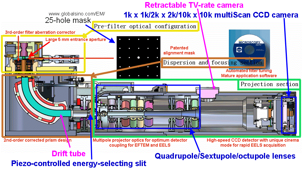
Figure 3939a. Schematic illustration of a GIF (Gatan Imaging Filter) camera.
Figure 3939b presents an example of automatic procedures to correct the magnification and aspect ratio of TEM (e.g. EFTEM) images with computer control. In this process, the imaged centers of the beam intensity distribution positions of the patterned beam scan are measured and applied to the adjustment.
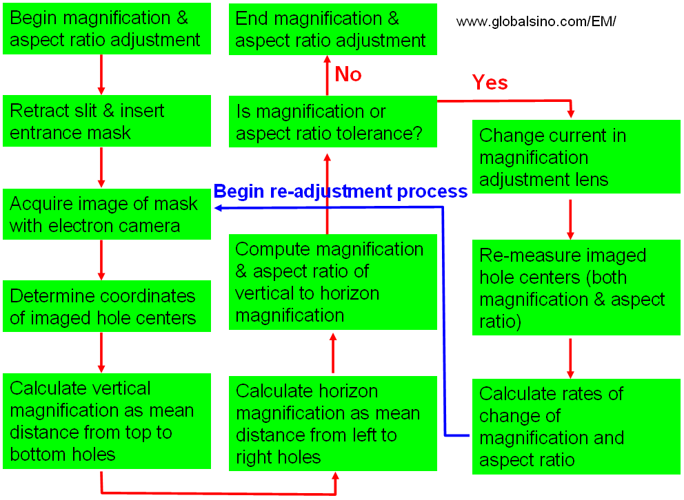
Figure 3939b. Example of automatic procedures to correct the magnification and aspect ratio of TEM (e.g. EFTEM) images with computer control.
Figure 3939c shows an example on how to correct the achromaticity in EFTEM mode. In this process, an energy offset is applied to the electron beam by changing the accelerating voltage at the electron gun of the TEM. The differences between the current positions of the hole centers of the mask and those measured before the change in beam energy are determined. The net average displacement is taken as a measure of the departure of the energy filtering system from the true achromatic imaging. If the net average displacement is not within the operator-specified tolerance, the effect on the average displacement to the changes in the current of a chromatic adjustment quadrupole lens of post-slit electron optics of the energy filtering system is assessed. These operations are iteratively performed if more precise achromatic adjustment is required or until the measured average displacement is within the specified tolerance.
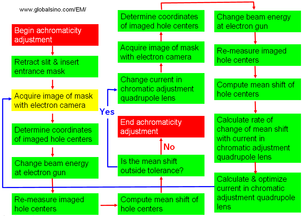
Figure 3939c. An example on how to correct the achromaticity.
Figure 3939d shows an example of procedures of image distortion correction in FETEM.
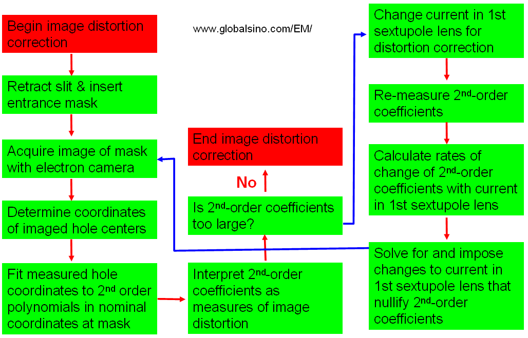
Figure 3939d. Example of procedures of image distortion correction in FETEM.
|