=================================================================================
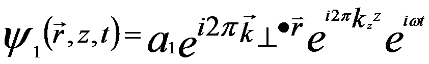
The plane wave of electron beam propagating in z-direction (optical axis) can be given by,
 ---------------------- [4202a] ---------------------- [4202a]
where,
a -- Amplitude
k -- Wavenumber (=1/λ)
λ -- Wavelength
ω -- Frequency
The vector r = (x, y) defines a position in a wavefront perpendicular to the electron propagation direction z. In off-axis electron holography as shown in Figure 4202, the plane wave of the electron beam is split to two partial waves which are deflected by a very small angle towards each other,
 (for x < 0 in Figure 4202) -------- [4202b] (for x < 0 in Figure 4202) -------- [4202b]
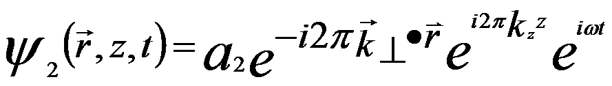 (for x > 0 in Figure 4202) -------- [4202c] (for x > 0 in Figure 4202) -------- [4202c]
where
k⊥ ≈ kβ/2
kz ≈ k
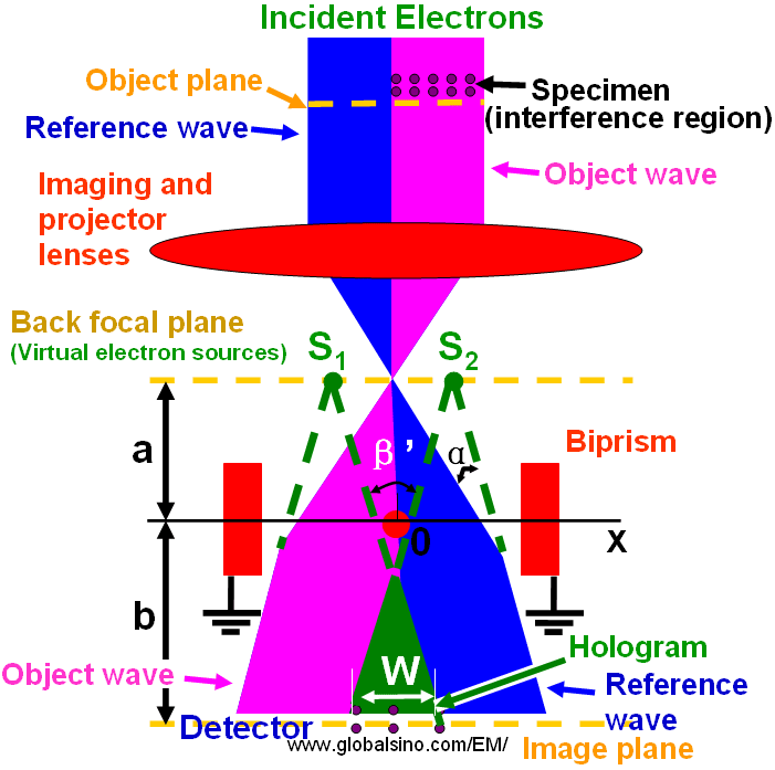
Figure 4202. Schematic diagram of off-axis electron holography in TEMs.
The two tilted waves are laterally shifted to the right (for the left part) and to the left (for the right part) by a width of W, respectively, and thus are superimposed in the hologram (W). In the point r of the detector the points  and and 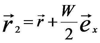 of the two partial waves with the unit vector ex in x direction, forming the intensity (I) in a format of cosinoidal interference pattern, of the two partial waves with the unit vector ex in x direction, forming the intensity (I) in a format of cosinoidal interference pattern,
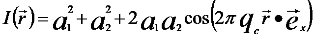 -------- [4202d] -------- [4202d]
where,
qc - Spatial frequency
(=kβ)
β -- The angle of the
superposition
The cosinoidal term produces the fringes in the measurements of off-axis electron holography.
|