=================================================================================
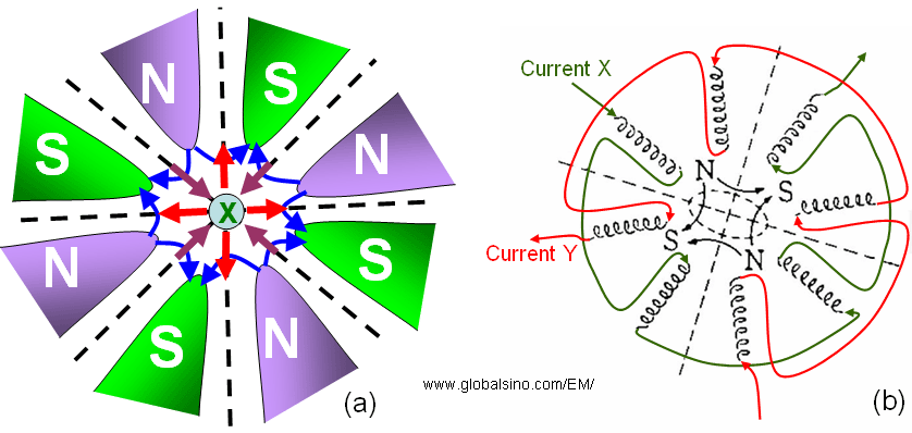
Figure 4315 shows the octupole design for spherical aberration (Cs) correction. The optical axis, along which the electrons travel, is into the page.  indicates the direction of the electron beam. The blue curves represent the magnetic field lines, while the red and plum arrowed lines represent the Lorentz force on the electrons. An octupole can be used to adjust a square distortion to the beam. Furthermore, from Equation 4313, we can know the field in the octupole system can be given by, indicates the direction of the electron beam. The blue curves represent the magnetic field lines, while the red and plum arrowed lines represent the Lorentz force on the electrons. An octupole can be used to adjust a square distortion to the beam. Furthermore, from Equation 4313, we can know the field in the octupole system can be given by,
 ---------------------------- [4315] ---------------------------- [4315]
Namely, it varies by r3, which acts directly as third order aberrations, increasing with distance from the optical axis. However, its lack of cylindrical symmetry can not lead to 3rd-order Cs when the paraxial optics is spherically symmetric, i.e. created by solenoid lenses.

Figure 4315. The octupole design for spherical aberration (Cs) correction: (a) The plum arrows show focusing function, while the red arrows show defocusing function, and (b) Formation of the magnetic field versus the electrical current directions in the octupole.
Combination of four magnetic quadrupoles with at least three octupoles [1] is normally employed for spherical aberration correction at high accelerating voltages in STEM system due to its off-axis aberrations.
[1] Krivanek, O. L., Dellby, N., and Lupin, A. R. 1999. Towards sub-Å electron beams, Ultramicroscopy, 78,
1–11.
|
 ---------------------------- [4315]