|
This book (Practical Electron Microscopy and Database) is a reference for TEM and SEM students, operators, engineers, technicians, managers, and researchers.
|
=================================================================================
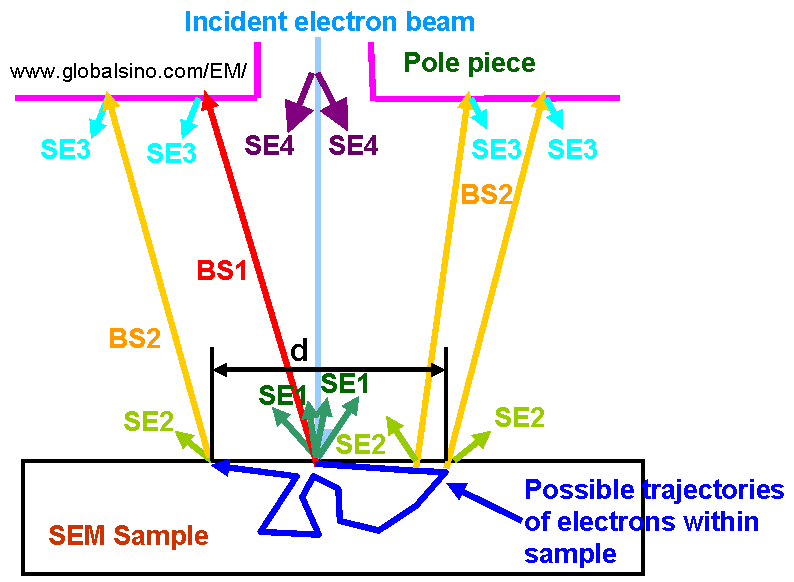
As shown in Figure 4558, SE3 generated at the objective lens pole piece in SEM can be minimized with a shield made of low SE emitting material, such as carbon-coated aluminum, placed immediately below the objective lens. A bias of + 50 V, applied to the shield, also prevents escape from the shield of any SE3. To increase atomic number contrast, BEs that strike the shield can he converted into SEs when the shield is positively biased or covered with a material that emits more secondary electrons. Refer to discussions provided by Reimer [1] and Peters [2].

Figure 4558. Source of Secondary Electrons in SEM. BS1 and BS2 are backscattering electrons; SE1 - SE4 are secondary electrons.
[1] Reimer, L., Scanning Electron Microscopy, Springer Verlag, New
York, 1985.
[2] Peters, K. R., "Conditions Required for High Quality High Magnification
Images in Secondary Electron-I Scanning Electron
Microscopy," SEM 1982, Vol. IV, SEM, Inc., Chicago, 1982, pp.
1359-1372.
|
