Table 958. Comparison between different correction methods.
| Method |
Correction principle and advantages |
Drawbacks |
|
This method is based on the approximation that the probability of electrons, entering the angle-limiting aperture is the same for both elastic and inelastic scattering processes |
This assumption is inaccurate in most cases since their scattering probabilities dependence on many factors such as TEM sample thickness and atomic numbers of the materials |
Mixed scattering
[1, 3] |
Corrections of both elastic and inelastic scattering effects had been considered |
i) The scattering is assumed to occur with the same cross-section as the average scattering cross-section, which is oversimplified
ii) No existing model to simulate the elastic scattering correction on complex materials by take the effects of all the different elements in the TEM sample |
Ratio method [1, 5] |
This method is based on the ratios of cross-sections and integrated intensities of two elements |
Absolute concentration cannot be obtained |
Elastic scattering [4] |
Correction of elastic scattering effect had been considered |
No existing model to simulate the elastic scattering correction on complex materials by take the effects of all the different elements in the TEM sample |
Plasmon shift correction [2] |
Plasmon shift correction, and
double scattering angular correction for small values of collection aperture (<10 mrad) |
i) Errors caused by multiple correction to the same scattering
ii) Correction of elastic scattering effect had not been considered |
|
i) Correction of inelastic scattering has been considered.
ii) Cross-section models: Hartree-Slater, Hydrogenic, Hydrogenic (white lines)
iii) Areal Density can be evaluated. |
|
| Power-law: better for background fitting for thin TEM sample and high energy core losses |
|
Software (DigitalMicrograph, DM) uses atomic cross sections that do not contain any near-edge fine structure. |
| 1st order log polynomial: better for background fitting immediately after plasmon tail and very thick TEM sample |
In Table 958, the mixed scattering method employed elastic and inelastic effects to correct the thickness effect of TEM sample. In this method, the core-loss and low-loss (plasmon) scatterings with the same energy window were taken into account in simple formula for the calculation of Areal Density, N.
In the thickness correction methods listed in Table 958, Mixed Scattering [1] and Elastic Scattering [4] methods considered the effect of angular distribution of elastic scattering. However, all of them do not have any existing model to simulate the elastic scattering correction on complex materials by take the effects of all the different elements in the TEM sample.
In the plasmon shift correction method [2], two correction terms, one related to a loss of collection efficiency after a shift in energy caused by multiple scattering and one related to a convolution of angular collection efficiencies caused by double scattering, had been employed for correction of core-loss signal. However, in this method, errors can be caused by multiple correction to the same scattering, and correction of elastic scattering effect had not been considered.
The advantage of Ratio Method is based on the ratios of cross-sections and integrated intensities of two elements:
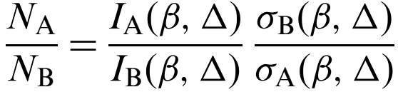 -------------------------------------- [958] -------------------------------------- [958]
where,
σA(β,Δ) and σB(β,Δ) -- the cross-section per atom for inner-shell scattering through angles up to a semi-angle β.
IA(β,Δ) and IB(β,Δ) -- the integrated intensity under the particular excitation edge, after subtracting a background.
This method is used to cancel the effects of several artefacts such as thickness effects and diffraction contrast. In this method, the low-loss region need not be measured unless it is required for deconvolution. However, this method cannot provide absolute concentrations without additional information.
[1] R.F. Egerton, Formulae for Light-Element Microanalysis by Electron Energy-Loss Spectrometry, Ultramicroscopy 3 (1978) 243.
[2] A. P. Stephens, Quantitative microanalysis by electron energy-loss spectroscopy: Two corrections, 5 (1–3) (1980), 343-349.
[3] R. F. Egerton, The Range of Validity of EELS Microanalysis Formulae, Ultramicroscopy 6 (1981) 297-300.
[4] K. Wong and R. F. Egerton, Correction for the effects of elastic scattering in core-loss quantification, Journal of Microscopy, 178 (3), (1995), 198-207.
[5] P. J. Thomas and P.A. Midgley, An introduction to energy-filtered transmission electron microscopy, Topics in Catalysis, 21 (4), (2002), 109.
|