Basic model statement in NgSpice:
model DMOD D
Code example:
circuit.model('TheDiode', 'D', IS=5@u_nA, RS=0.7@u_Ω, BV=100@u_V, IBV=0.0001@u_V, N=2)
where,
IS -- A parameter of dc characteristics of the diode,
RS -- An ohmic
resistance,
BV -- A parameter determines the exponential increase in the reverse diode current on reverse breakdown,
IBV -- Another parameter determines the exponential increase in the reverse diode current on reverse breakdown,
N -- Another parameter of dc characteristics of the diode,
TT -- A transit time to model charge storage effects,
CJO -- A parameter to determine a nonlinear depletion layer capacitance,
VJ -- Another parameter to determine a nonlinear depletion layer capacitance,
M -- The third parameter to determine a nonlinear depletion layer capacitance,
EG -- The energy which defines the temperature dependence of the saturation current,
XTI -- The saturation current temperature exponent which defines the temperature dependence of the saturation current,
TNOM -- A parameter measures the nominal temperature and defaults to the circuit-wide value specified on the .options control line.
Table 4694. Junction DC parameters for NgSpice simulations of diodes. [1]
| Name |
Parameter |
Units |
Default |
Example |
Scale factor |
| IS (JS) |
Saturation current |
A |
1.0e-14 |
1.0e-16 |
area |
| JSW |
Sidewall saturation current |
A |
0.0 |
1.0e-15 |
perimeter |
| N |
Emission coefficient |
- |
1 |
1.5 |
|
| RS |
Ohmic resistance |
Ω or Ohm |
0.0 |
100 |
1/area |
| BV |
Reverse breakdown voltage |
V |
∞ |
40 |
|
| IBV |
Current at breakdown voltage |
A |
1.0e-3 |
1.0e-4 |
|
| NBV |
Breakdown emission coefficient |
- |
N |
1.2 |
|
| IKF (IK) |
Forward knee current |
A |
0.0 |
1.0e-3 |
|
| IKR |
Reverse knee current |
A |
0.0 |
1.0e-3 |
|
| JTUN |
Tunneling saturation current |
A |
0.0 |
|
area |
| JTUNSW |
Tunneling sidewall saturation current |
A |
0.0 |
|
perimeter |
| NTUN |
Tunneling emission coefficient |
- |
30 |
|
|
| XTITUN |
Tunneling saturation current exponential |
- |
3 |
|
|
| KEG |
EG correction factor for tunneling |
- |
1.0 |
|
|
| ISR |
Recombination saturation current |
A |
1e-14 |
1pA |
area |
| NR |
Recombination current emission coefficient |
- |
1 |
2 |
|
| CJO (CJ0) |
Zero-bias junction bottom-wall capacitance |
F |
0.0 |
2pF |
area |
| CJP (CJSW) |
Zero-bias junction sidewall capacitance |
F |
0.0 |
.1pF |
perimeter |
| FC |
Coefficient for forward-bias
depletion bottom-wall
capacitance formula |
- |
0.5 |
- |
|
| FCS |
Coefficient for forward-bias
depletion sidewall capacitance
formula |
- |
0.5 |
- |
|
| M (MJ) |
Area junction grading coefficient |
- |
0.5 |
0.5 |
|
| MJSW |
Periphery junction grading coefficient |
- |
0.33 |
0.5 |
|
| VJ (PB) |
Junction potential |
V |
1 |
0.6 |
|
| PHP |
Periphery junction potential |
V |
1 |
0.6 |
|
| TT |
Transit-time |
sec |
0 |
0.1 ns |
|
Figure 4694 shows an example which includes a diode.
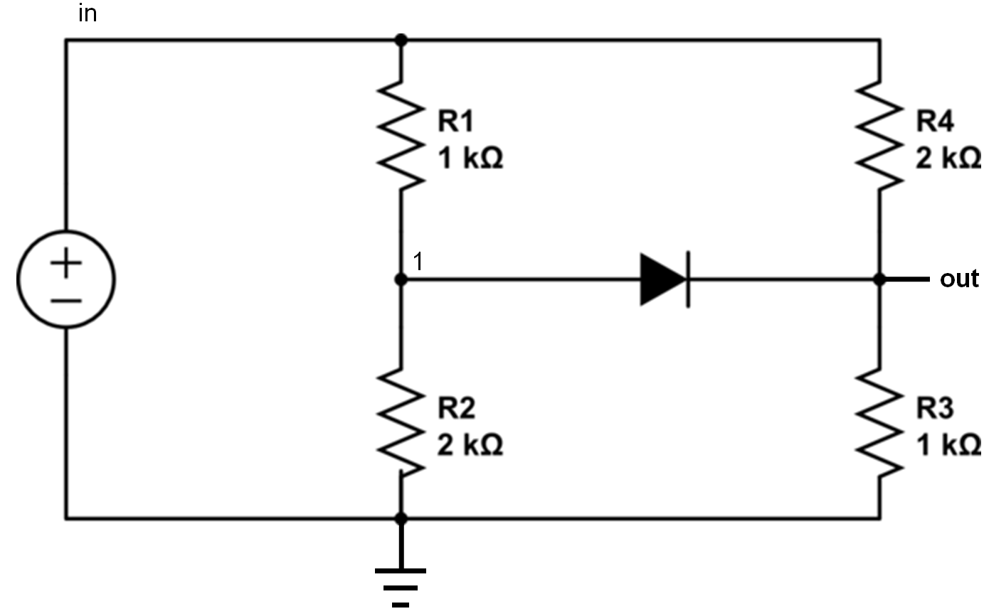
Figure 4694. Electrical circuit with a diode.
=================================================
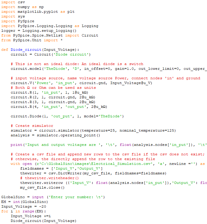
Simulation of electrical circuits with a diode (Figure 4694): code:
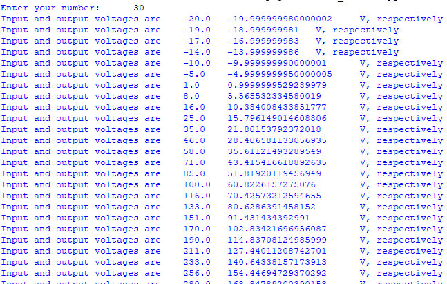
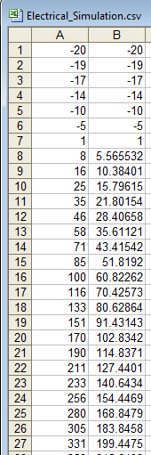
Output:
[1] NgSpice Manual.
|