| The lock-in principle is a preferred technique for extracting signals from statistical noise. To use this method, the primary signal (before detection and the first amplification stage) must be periodically pulsed or amplitude-modulated at a specific frequency, known as the 'lock-in frequency' (flock-in). In some experiments, such as cyclical mechanical loading, this modulation naturally occurs. In cases where light generates the primary signal, like in light absorption experiments, mechanical chopping of the light beam or turning the light on and off can create an amplitude-modulated signal.
Figure 0795a illustrates the lock-in principle.

Figure 0795a. Lock-in principle: (a) Primary signal which is a sine wave with a set frequency (frequency_signal = 10 Hz), representing the original signal, (b) Modulation signal (lock-in frequency) which is a slower sine wave modulation (modulation_frequency = 1 Hz) that applies the lock-in frequency to the primary signal, and (c) Modulated signal, which is the result of multiplying the primary signal by the modulation signal, creating the modulated output. |
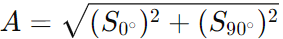
The amplitude
A of the signal
can be calculated by combining the in-phase (S0°) and quadrature (S90°) components, given by,
 --------------------------------------------------- [0795a]
These components are signals that are 90 degrees out of phase with each other, representing the real and imaginary parts of the signal in the complex plane. By taking the square root of the sum of their squares, the total amplitude of the modulated signal is obtained, which corresponds to the overall strength of the detected signal after lock-in processing.
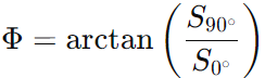
The phase
Φ of the signal relative to a reference signal
can be calculated by,
 --------------------------------------------------- [0795b] --------------------------------------------------- [0795b]
The phase in Equation 0795b is determined using the arctangent of the ratio between the quadrature component (S90°) and the in-phase component (S0°). This provides the time shift or delay of the signal in relation to the reference, which is crucial in understanding the behavior of the signal with respect to its modulation source.
The two equations, Equation 0795a and 0795b, are fundamental for analyzing signals in the lock-in detection process and are essential for extracting both the magnitude and temporal characteristics of a signal in lock-in detection.
Figure 0795b shows amplitude (A) and phase angle (Φ) as a function of S0° and S90°.
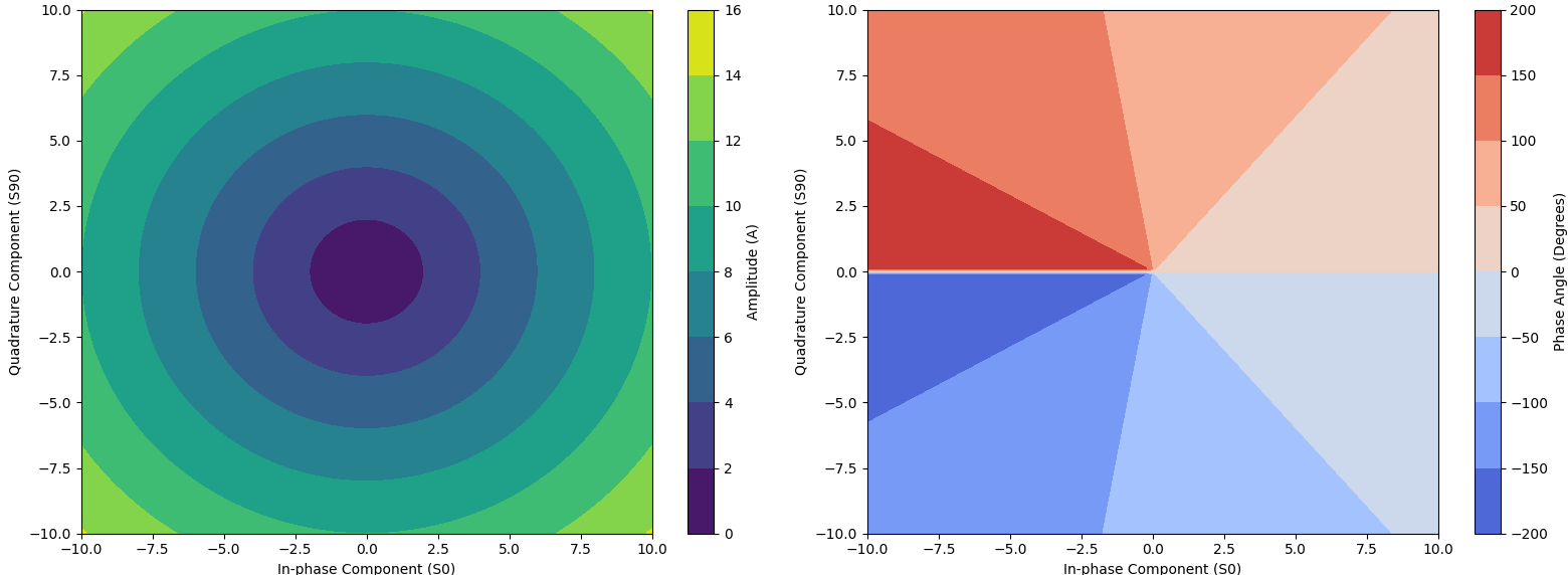
Figure 0795b. (a) Amplitude (A), and (b) Phase angle (Φ) as a function of S0° and S90°. |
The lock-in amplifier works in a very targeted and non-random way to enhance the desired signal and suppress unwanted noise:
- Reference Signal (Lock-in Frequency):
The key to the lock-in amplifier's operation is that it uses a reference signal at a known frequency, which is often generated by the system itself or is related to the experiment being conducted. This reference signal is called the lock-in frequency. The modulation signal in Figure 0795a (b) represents the reference signal in the lock-in technique.
- For example, if you're modulating a light beam at 100 Hz (turning it on and off), this 100 Hz frequency becomes the lock-in frequency.
- The lock-in amplifier is "tuned" to this frequency, meaning it will look for signals at exactly 100 Hz (or whatever the modulation frequency is).
- Suppressing Noise:
Noise, by nature, is random and spread across many frequencies. It usually doesn’t have a specific periodic pattern like your modulated signal. The lock-in amplifier is able to suppress these random noise components because they don't match the frequency of the reference signal. - For example, a random noise signal might include components at 50 Hz, 200 Hz, or other frequencies. The lock-in amplifier filters out these components and only enhances the signal at 100 Hz.
- Even if some noise happens to overlap with the 100 Hz frequency, its contribution is usually much weaker compared to the modulated signal, so its impact is minimized.
In Lock-in Thermography (LIT), the lock-in frequency and the reference signal are crucial components that allow for the detection of thermal signals from an object under test:- Lock-in Frequency:
- The lock-in frequency in Lock-in Thermography refers to the frequency at which the thermal excitation is modulated (turned on and off or pulsed) to induce a periodic heat flow in the sample.
- This frequency is typically chosen by the user and can vary depending on the system and the material being tested. It is usually in the range of a few mHz to a few Hz, depending on how fast the thermal response of the material is.
For example:
- For slow-responding materials (like thick materials with slow heat diffusion), a lower lock-in frequency (e.g., 0.01 to 0.1 Hz) is used. The main reasons are:
- Thick metals have slow thermal diffusion, meaning it takes longer for heat to propagate through the material.
- Lower lock-in frequencies allow enough time for the heat to spread.
- For faster-responding materials (like thin materials), a higher lock-in frequency (e.g., 1 to 10 Hz) can be used. The main reason is:
- Thin materials heat and cool quickly, allowing the use of higher frequencies to capture rapid thermal responses.
- Polymer and Composite Materials:
- Lock-in frequency: 0.1 to 1 Hz.
- Reason: Polymers and composites generally have lower thermal conductivity, so moderate lock-in frequencies are chosen to track thermal diffusion without overheating.
- Semiconductor Wafers:
- Lock-in frequency: 1 to 5 Hz.
- Reason: Semiconductor materials like silicon typically require moderate frequencies due to their balanced thermal conductivity and rapid heat diffusion in thin wafers.
- Ceramic Materials:
- Lock-in frequency: 0.01 to 0.5 Hz.
- Reason: Ceramics are generally poor conductors of heat, requiring lower frequencies to allow heat propagation through the material for effective defect detection.
- Reference Signal:
- The reference signal in Lock-in Thermography is typically the signal that drives the thermal excitation, such as the power supply controlling the heating source (e.g., laser, lamp, or another heat source).
- This reference signal is synchronized with the thermal excitation and is used by the lock-in system to detect thermal changes at the same frequency (lock-in frequency) as the applied excitation.
- The lock-in amplifier uses this reference signal to extract the modulated thermal response (temperature variations) from the material, filtering out noise at other frequencies.
- Frequency of the Reference Signal:
- The frequency of the reference signal is exactly the same as the lock-in frequency because the reference signal is the signal that modulates the heat source.
- If you are modulating the heating source at, for example, 1 Hz, then the reference signal is also at 1 Hz, which is the same frequency at which the lock-in amplifier will look for the thermal response.
- Steps of how it works in Lock-in Thermography:
- Thermal Excitation: A heat source (laser, lamp, etc.) is pulsed or modulated at a specific frequency (the lock-in frequency).
- Thermal Response: The object under test absorbs heat and then re-emits it, creating a thermal signal that follows the periodic heating.
- Reference Signal: The system tracks the reference signal (which controls the heat source) and uses it to synchronize the detection of the thermal signal.
- Detection: The lock-in amplifier extracts the thermal response that matches the reference signal frequency, filtering out noise and background temperature variations.
|
