=================================================================================
The alignment of objective lens in EMs is very critical and needs to be performed extremely carefully. Misalignment of the objective lens increases the spherical aberration and the sensitivity of the chromatic aberration so that it seriously reduces the resolving power of the microscope. As an example, Figure 1981a shows the misalignment of an objective lens, where the off-axis electron beam enters the objective lens. For a specific lens setting, the object ABC forms an image A'B'C'. The image will be changed to A"B"C" (smaller than A'B'C') with a center (B' or B”) formed by the unchanged beam (BB' or BB”) if the objective lens setting is changed. In this case, the back focal plane of the objective lens is also changed. Furthermore, as shown in Figure 1981a (b) this change induces a rotation of the image because of the helical path of the electrons through the lens. This can happen, for instance, when the objective lens current is changed.
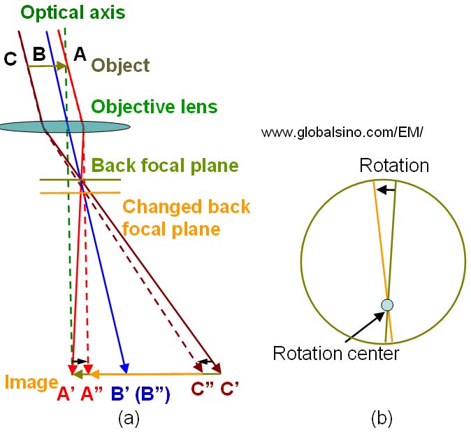
Figure 1981a. Misalignment of the objective lens: (a) Sweep of the image, and (b) Combination of sweep and rotation of the image on the viewing screen in the EM.
The beam misalignment can be corrected either by tilting the incident illumination as shown in Figure 1981b (a), or by adjusting the physical position of the objective lens pole pieces as shown in Figure 1981b (b). In Figure 1981b (b) the lower pole piece in TEM is moved so that both upper and lower pole pieces are aligned to the optical axis.
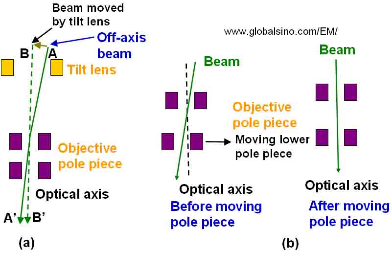
Figure 1981b. The correction of non-axial objective lens illumination by: (a) Beam tilt, and (b) Movement of the lower objective lens pole piece.
Finally, the beam alignment can be conformed by viewing the rotation center of the image on the viewing screen when the defocus of the objective lens is adjusted. If the rotation center of the image matches the center of the viewing screen, the beam alignment around the objective lens is correct.
|