Cockcroft–Walton Voltage-Multiplier Circuit Generator - Practical Electron Microscopy and Database - - An Online Book - |
||||||||
| Microanalysis | EM Book http://www.globalsino.com/EM/ | ||||||||
| This book (Practical Electron Microscopy and Database) is a reference for TEM and SEM students, operators, engineers, technicians, managers, and researchers. | ||||||||
| ================================================================================= | ||||||||
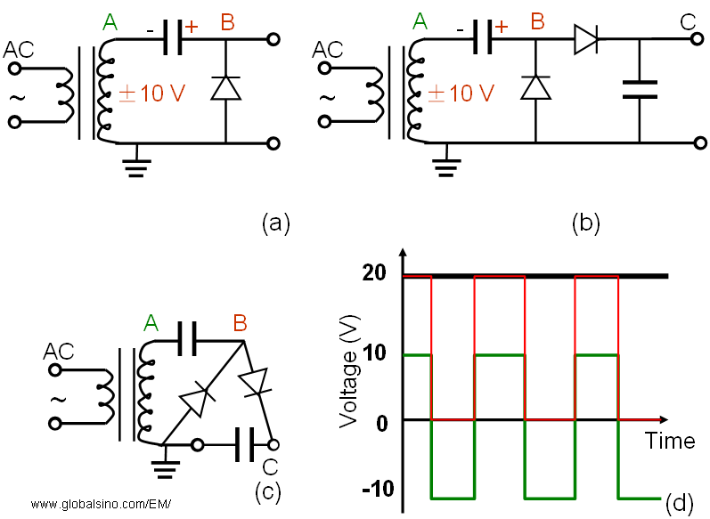
Historically, the instability of the high voltage of TEM systems had been one of the major problems behind the resolution improvement. To achieve atomic resolution, one needs the stability in the range of one part per million (1 ppm). For this purpose, Cockcroft–Walton voltage generator has been used to supply the high voltage to the electron guns and a negative feedback system is also used. The Cockcroft–Walton (CW) voltage-multiplier circuit generator is an electric circuit that has been used to generate high DC voltages from low AC (alternating current) or pulsing DC (direct current) voltages. The British and Irish physicists, John Douglas Cockcroft and Ernest Thomas Sinton Walton, used this type of circuits to power their particle accelerator to perform the first nuclear disintegration in 1932 and won the Nobel Prize in the title of "Transmutation of atomic nuclei by artificially accelerated atomic particles" in Physics in 1951. Cockcroft–Walton (CW) voltage generators are based on voltage doublers. A voltage doubler is an electronic circuit that produces twice the input voltage by charging a capacitor from the input voltage. Figure 3257a shows one of the simplest circuits, composed of a transformer, a capacitor, and a diode. We assume that with AC input the capacitor is always charged at +10 V due to the diode, when there is no load. This charging process occurs when the voltage at A becomes lower than GROUND, and then the electric current flows to B through the diode D. Note the capacitor is charged up with electrons Q = CV (Here, C is the capacity between A and B). When A (green) is at +10 V, then B (red) is at +20 V because the transformer and capacitor are in series, while B is at 0 V when A is at -10 V. Therefore, the output voltage at B is twice the voltage at A. Note that the voltage at B is still an AC voltage. In order to obtain a DC voltage, an extra capacitor and a diode are added as shown in Figure 3257a (b). Figure 3257a (c) is obtained only by tightening Figure 3257a (b).
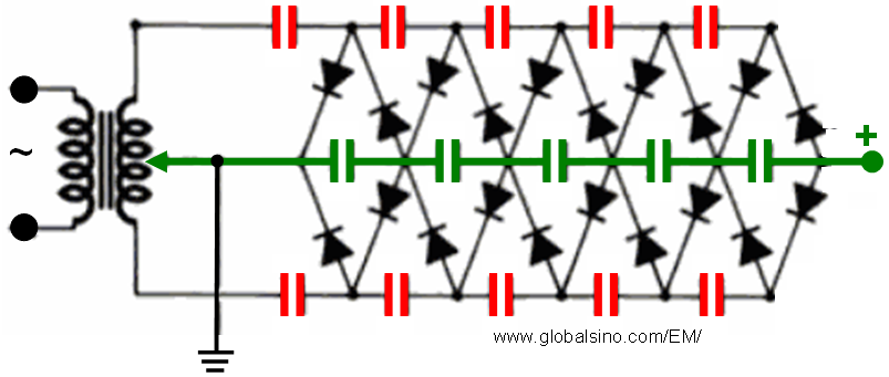
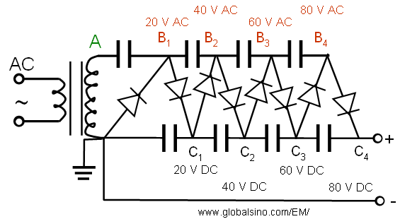
Figure 3257a. (a) One of the simplest voltage doublers, (b) The circuit to obtain DC voltage, (c) The equivalent draw of (b), (d) The ideal first output voltage (B, in red) and final output voltage (C, in black) as a function of input voltage (A, in green) with the voltage doubler in (a). By repeating the unit (stage) in Figure 3257a (c), Cockcroft–Walton voltage-multiplier circuit generator can be obtained. For instance, Figure 3257b shows four-stage a Cockcroft–Walton voltage generator. Note that the stages do not really double the voltages, but they just shift the input voltages higher and higher each stage.
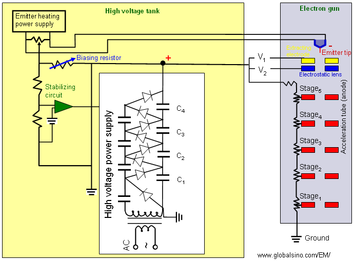
Figure 3257b. Cockcroft–Walton voltage-multiplier circuit generator. The output of Cockcroft–Walton voltage generator is then connected to the electrode stages in the accelerator tube as shown in Figure 3257c. Each electrode stage is powered by a divided voltage supplied through the bleeder resistors that are connected to the output of the voltage generator.
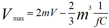
Figure 3257c. Electronic connection between Cockcroft–Walton voltage generator and accelerator tub in TEMs. In reality, the capacitors are not charged fully so that the maximum voltage obtained (Vmax) for an m-stage Cockcroft–Walton circuit can be given by, The high-voltage generated with a high-voltage generator is supplied to acceleration tube through the high voltage cable of electron microscopes, and thus the electrons are accelerated in the acceleration tube. The circuit in Figure 3257c is practically used in most conventional microscope power supplies. However, for the microscopes operating at voltages higher than 300 kV, two such circuits are often mirrored as shown in Figure 3257d.
Figure 3257d. Mirrored Cockcroft–Walton voltage generator.
|
||||||||
| ================================================================================= | ||||||||
| The book author (Yougui Liao) welcomes your comments, suggestions, and corrections, please click here for submission. If you let book author know once you have cited this book, the brief information of your publication will appear on the “Times Cited” page. | ||||||||
|
|
||||||||
 ------------------------ [3257a]