=================================================================================
In most modern, practical TEMs/STEMs, the gun lens is used to position the first crossover in relation to the beam-defining aperture (normally the C2 aperture). The crossover locates high above the aperture with a strong gun lens, while the crossover is close to the aperture with a weak gun lens. Both the beam current and aberrations on the beam are higher for the latter case. Therefore, when small, intense and low-aberration electron beams are needed, e.g. for diffraction in TEM and analytical STEM, a strong gun lens is selected; while a weak gun lens is selected when high probe currents are needed (e.g. TEM imaging). Note that the TEM system will automatically select the relevant strength of the gun lens once the users push a bottom of STEM, diffraction, or TEM modes even though they have realized the strength changes.
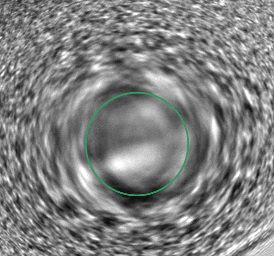
In STEM operation, to observe the Ronchigram, the apertures after the specimen are removed and a large probe convergence angle (>100 mrad) is selected, for instance by inserting the largest STEM objective aperture (condenser aperture in CTEM). The Ronchigram can then be directly observed on the microscope phosphor screen or TV-rate CCD camera. Figure 3584 shows a Ronchigram pattern taken at Gaussian focus from an amorphous thin film in TEM. The green circle marks the unaberrated part of Ronchigram that should be selected by objective aperture for STEM imaging.

Figure 3584. Ronchigram pattern taken at Gaussian focus.
By wobbling the condenser lens excitation and then the microscope high tension, the alignment of the illumination electron beam in STEM mode can be very accurately checked. If there is a misalignment of the beam between condenser and objective lenses, there will be a periodic translation of Ronchigram features when the wobbling takes place. This misalignment can be corrected by using the condenser alignment coils (CTEM bright tilt in JEOL systems) so that the features only oscillate in and out symmetrically about the coma-free axis.
Table 3584. Example of operating conditions of STEM imaging.
TEM/STEM model |
Probe size |
Probe current |
Convergence semi angle |
HAADF collection semi-angle |
BF correction semi-angle |
Aberration corrector |
Application |
JEM-ARM200F |
0.08 nm |
9 pA |
22 mrad |
40-110 mrad |
7 mrad |
Yes |
Atomic resolution |
X-FEG/Titan G2 |
0.31 nm |
< 8 nA |
|
|
|
Yes |
Atomic resolution |
X-FEG/Titan G2 |
<0.1 nm |
0.6 nA |
|
|
|
Yes |
Atomic resolution |
X-FEG/Titan G2 |
0.2 nm |
250 pA |
|
|
|
No |
|
|