=================================================================================
Because of the dependence of beam size on diffraction and aberrations as shown in Figure 3648a, in order to achieve the optimum performance the diffraction and aberrations should be balanced as indicated by the optimum convergence semi-angles. For big electron sources, at low convergence semi-angles (α), the diffraction mainly determines the beam size, while at high α the spherical aberration is the dominant factor.
The diffraction term is given by,
dd=0.61λ/α ----------------- [3648a]
The spherical aberration term is given by,
ds=1/2Csα3 -------------------------- [3648b]
where,
λ -- The wavelength of the incident electron beam,
Cs -- The spherical aberration coefficient,
α -- The convergence semi-angle.
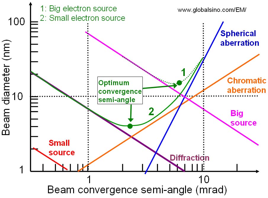
Figure 3648a. Diameter of the electron-beam as a function of beam-convergence semi-angle. 1: big electron source. 2: small electron source.
The achievable instrumental performance of a STEM is mainly determined by the size and shape of the incident electron probe. The most important optical factor in achieving the optimum probe profile is the radius of the probe-forming aperture, which determines the convergence semi-angle of the illumination. Small deviations from this optimum can degrade both the resolution and interpretability of the image contrast.
After the corrections of lower order aberrations, the corrector normally introduces or leaves high order aberrations. For instance, the Ronchigram with a 54 mR aperture indicated in Figure 3648b shows the left 4th order coefficient of order 0.5 - 2.0 mm limiting the probe shape and size after 3rd order aberration correction by Nion quadrupole-octupole corrector. The pattern is strongly 4-fold symmetry with weak 2-fold structure in the opposing corners. Note that this uniform 4-fold symmetry was actually imposed by the octupoles in the corrector, so called parasitic aberrations.
Figure 3648b. Ronchigram obtained with 4th order coefficients corrected to < 60 µm [1].
[1] P. E. Batson, Control of Parasitic Aberrations in Multipole Corrector Optics, Microsc Microanal 14(Suppl 2), 2008.
|