=================================================================================
Magnification of a microscope is controlled by the camera length L of the
diffraction pattern (DP), and this is given by
L = D/M --------------------------------------------------------------- [1932]
where D is the distance from the projector crossover to
the recording plane (e.g. phosphor screen)and M is the magnification of the
image in that plane. For instance, if D is about 600 mm and the
screen magnification is 20,000 x then camera length (L) is 0.03 mm.
Different camera lengths are available by turning the magnification knob but this does not affect the imaging magnification when you return to image mode.
In Figure 1932a (a), the spectrum is formed in the dispersion plane, consisting of a distribution of electron counts (I) versus energy loss (ΔE). All the electrons suffering the same energy loss but traveling in both on-axis and off-axis directions are directed to a focus in the dispersion plane of the spectrometer, which acts as a homogenous magnetic lens as shown in the equivalent schematics in Figure 1932a (b). The object plane of the spectrometer is typically set at the back focal plane (crossover) of the projector lens.
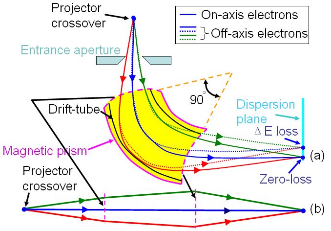
Figure 1932a. (a) Schematic showing magnetic prism, and (b) Equivalent schematics of the magnetic prism. Electrons at various
kinetic energies (due to energy losses induced by interaction with TEM specimen) are focused at the energy-dispersive plane of the spectrometer.
For the most common EFTEM unit as shown in Figure 1932b, the detection system consists of a slow scan CCD array detector rather than a single line of diodes used in PEELS detector.
Figure 1932b. Gatan imaging filter using CCD detector.
|