=================================================================================
In order to improve the resolution in his electron microscope, Dennis Gabor initially proposed a technique to “read” optically electron micrographs that suffered from severe spherical aberrations [1] in 1947 when he worked at British Thomson-Houston. However, the name, holography, was later chosen to indicate that this technique records the entire field information (i.e. amplitude and phase) not just the usual intensity. Gabor was awarded the Nobel Prize in Physics “for his invention and development of the holographic method” in 1971. The holography developed by Gabor is also called in-line holography or point projection holography.
The in-line holography means that both the reference and object waves share the same optical axis. In this technique as shown in Figure 2614a, an object is placed into divergent electron beam, where part of the wave is scattered by the object (called object wave) and interferes with the unscattered wave (called reference wave) in detector plane. The spatial coherence is determined by the size of the electron source.
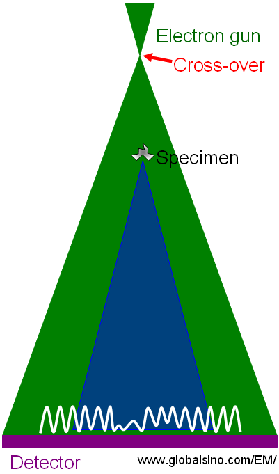
Figure 2614a. Simple example of in-line holography techniques.
Holography is essentially a two-step process:
i) Writing a hologram.
ii) Reading the hologram.
Figure 2614b shows that a point source of monochromatic rays is collimated by a lens and the ray scattering at the edges of a small particle creates a diffraction pattern through interference with the unscattered background illumination. The detector or films records an intensity distribution generated by the interference. The fringe frequency increases with the angle between scattered and unscattered background rays. The fringe contrast decreases when the path difference between the diffracted and background rays increases with the diffraction angle (indicated by the red curve). The process of fringe formation is called “writing a hologram”, which involves recording both the amplitude and phase information.
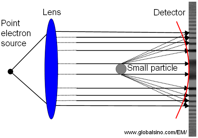
Figure 2614b. Schematic illustration showing that the ray scattering at the edges of a small particle creates a diffraction pattern through interference with the unscattered background illumination.
The intensity of the diffraction pattern can be given by,
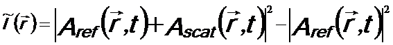 ------------------ [2614a.a] ------------------ [2614a.a]
 ------------ [2614a.b] ------------ [2614a.b]
The first term in Equation 2614a.b is the holographic term, while the second term is the classical diffraction term.
Figure 2614c shows the obtained hologram (the photograph of the diffraction pattern) is illuminated with the original beam and the rays are diffracted into the -1st order, resulting in a virtual image (called virtual reconstruction) of the original object, which is no longer present.
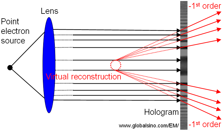
Figure 2614c. Schematic illustration of rays diffracted into the -1st order.
Figure 2614d shows the obtained hologram is illuminated with the original beam and the rays are diffracted into the +1st order, resulting in a real image (called real reconstruction) of the original object.
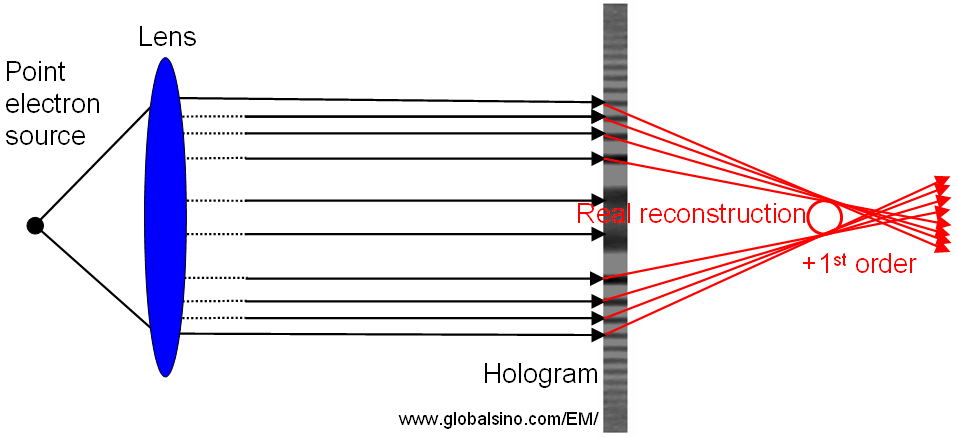
Figure 2614d. Schematic illustration of the rays diffracted into the +1st order.
Another reason that this technique is called in-line holography is that the virtual, real, and zero-order non-diffracted rays are all in-line as shown in Figure 2614e. However, because the real and virtual (so-called twin) images cannot be optically separated, their positions deteriorates the quality of the reconstruction.
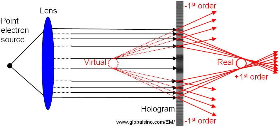
Figure 2614e. The virtual, real, and zero order non-diffracted rays in in-line holography.
Note that the processes shown in Figures 2614c, 2614d, and 2614e are called “reading the hologram”.
[1] D. Gabor, A new microscopic principle, Nature, 161, 777 (1948).
|