=================================================================================
Optical aberration can be described by the so-called wave aberration functions. There are two types of aberrations:
i) Coherent aberrations falsify amplitude and phase information of the wave [2],
ii) Incoherent aberrations act like a soft aperture due to the lack of spatial and temporal coherence [3].
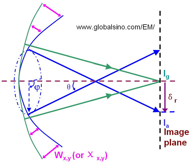
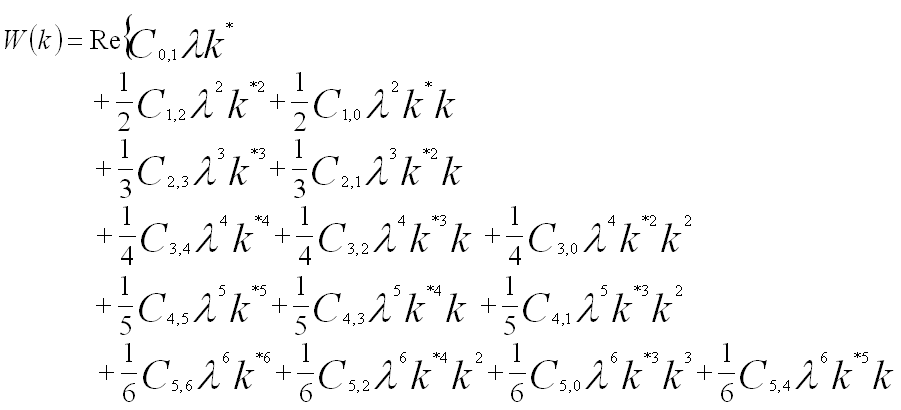
Coherent aberrations have been widely discussed. For the ideal cases without aberrations, when an object is imaged using a perfect lens the wave at the back focal plane of a lens is spherical and is converged in the image plane (Ig) as shown in Figure 3749. In other words, the ray aberration of a ray leaving an object point with a diffraction vector g is given by the displacement vector δr(g) from the ideal Gaussian image point to the point where the ray, after passing through the lens, intersects the image plane. The wave aberration function is defined as the phase difference (χx,y) or the distance difference (Wx,y) in the optical path from the perfect (reference) spherical wave to the actual wavefront for the given lens. The relationship between the phase difference (χx,y) and the distance difference (Wx,y) can be given by,
 ------------------------- [3749a] ------------------------- [3749a]
where ,
λ -- The wavelength of the electron wave

Figure 3749. Schematic illustration of wave aberration function (Wx,y or χx,y) and ray aberration (δr).
In some cases for the convenience of theoretical expressions, the wave aberration function is simply given by the distance between the intersecting points (on the image plane) of the ideal ray and the aberrated ray indicated in in Figure 3749. The distance (also called ray aberration), δr is given by,
 --- [3749b] --- [3749b]
The ray aberration is proportional to the gradient of the wave aberration Wx,y. The ray aberration is linked to the wave aberration by, [1]
 ---------------------- [3752j] ---------------------- [3752j]
where,
ω -- (= λg) the related complex scattering angle,
ϖ -- The complex conjugate of ω.
[1] Lichte, H. (1991). Optimum focus for taking electron holograms. Ultramicroscopy 38, 13–22.
[2] Hanßen, K.-J. (1971). The optical transfer theory of the electron microscope: Fundamental principles and applications. Adv Optics
Electron Microsc 4, 1–84.
[3] Frank, J. (1973). The envelope of electron microscopic transfer
functions for partially coherent illumination. Optik 38, 519–536.
|
 ------------------------- [3749a]
 --- [3749b]