=================================================================================
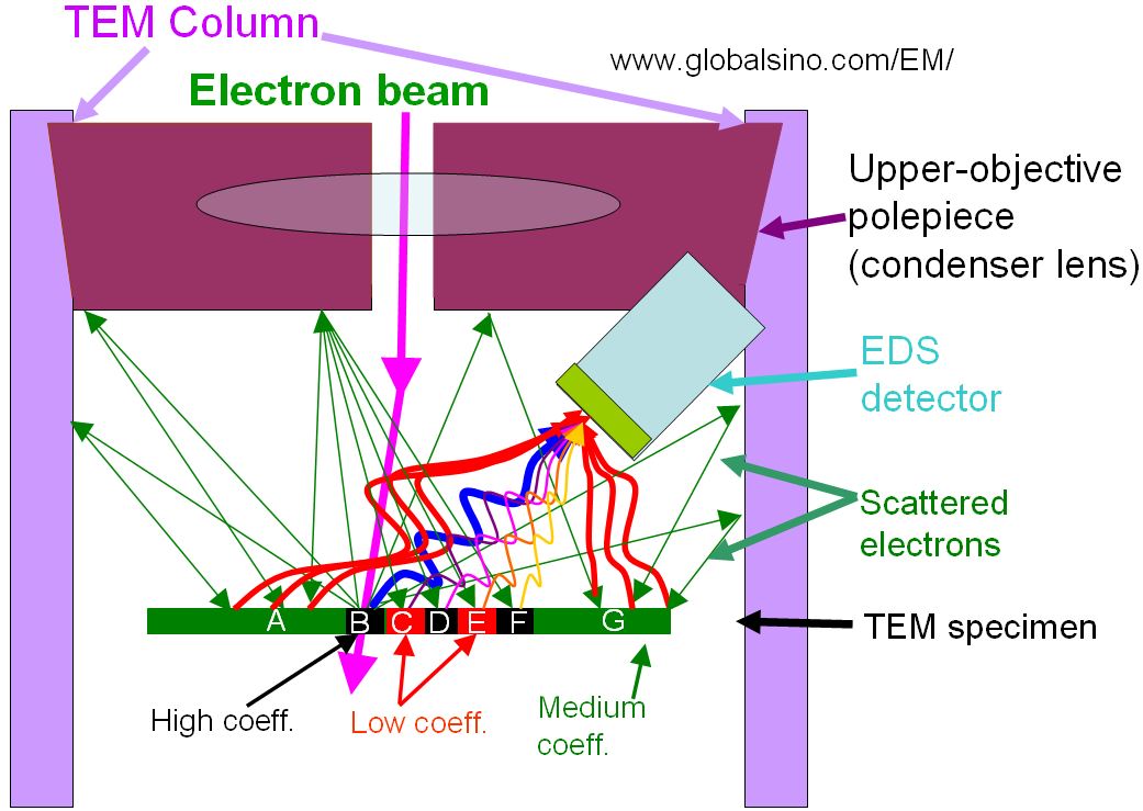
Incident electrons are partially scattered at the probing spot on the TEM specimen. Figure 3815a (a) shows the backscattered electrons from the specimen are then partially scattered back to everywhere on the specimen, and generate X-rays from all the materials everywhere on the specimen and even the TEM chamber. Some of such X-rays travel towards the EDS detector and thus contribute to the X-ray signal. Therefore, the X-rays collected by the EDS detector at any time is the sum of the X-rays collected from the probing spot and those, generated by the scattered electrons, from all the materials everywhere on the TEM specimen, given by:
Itotal = IP(t, d) + IS(t, A) ----------------------------------- [3815]
where,
IP -- X-rays collected from the probing spot, which is a function of the thickness of the probing area (t) and probe size (d).
IS -- X-rays, generated by the scattered electrons, from all the materials everywhere on the TEM specimen, which is a function of the specimen
thickness (t) and entire backscattering area (A).
In Equation 3815, we assume the thickness of the probing area and the
thicknesses of the other areas on a specimen are the same (= t); however, in reality, the thicknesses can vary significantly from the probing area, across the entire specimen, on the specimen grid, on the TEM specimen holder to the TEM column, and they are different from a TEM system to another. The second term, IS, does not contribute to EDS signal of the area of interest (AOI) but make the EDS data more complex by adding artifacts. Figures 3815a (b-d) shows X-ray generation behavior due to combination
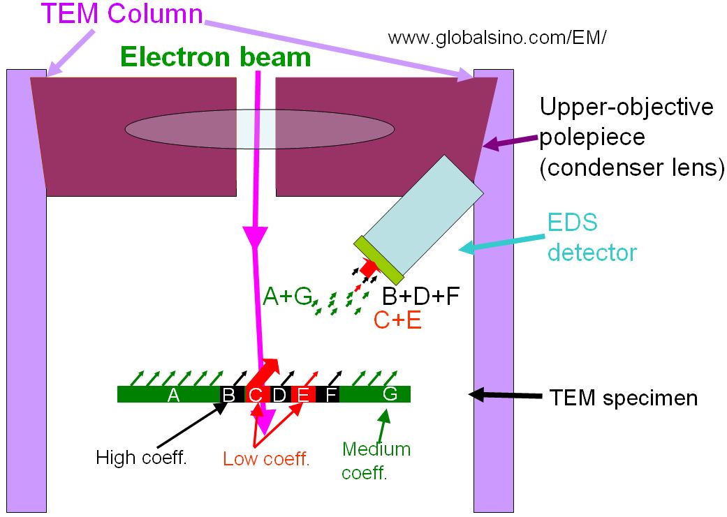
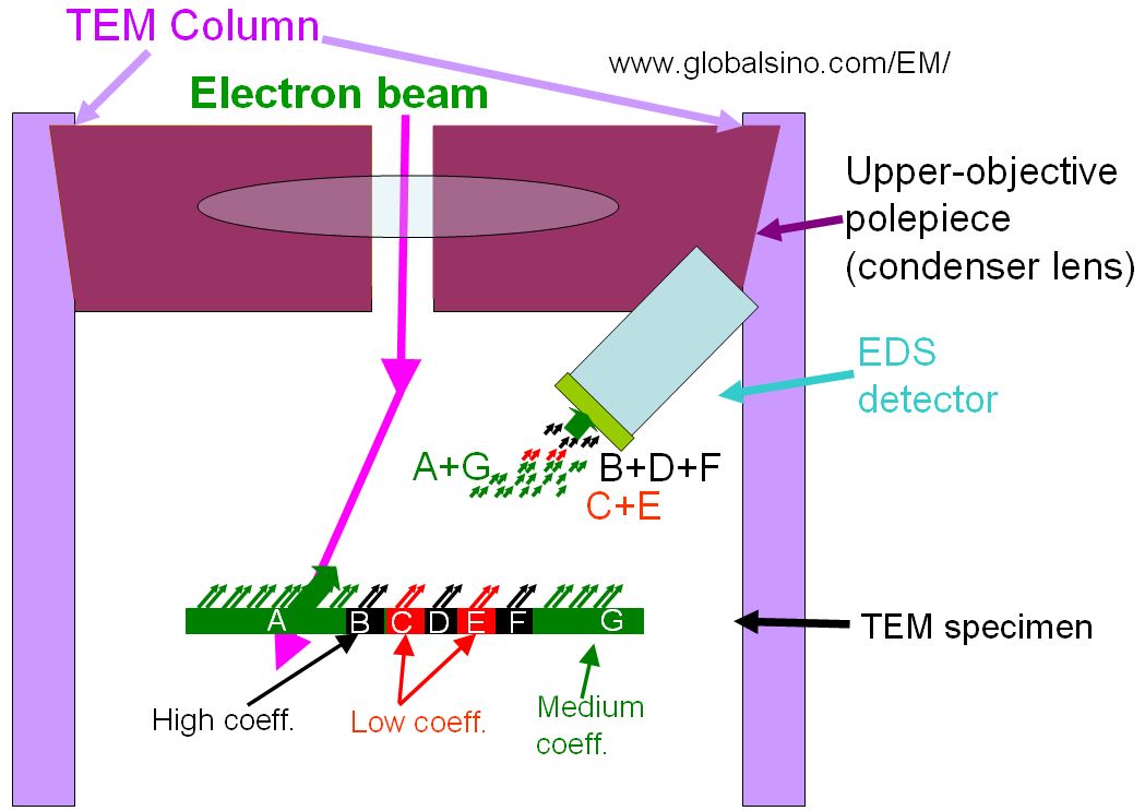
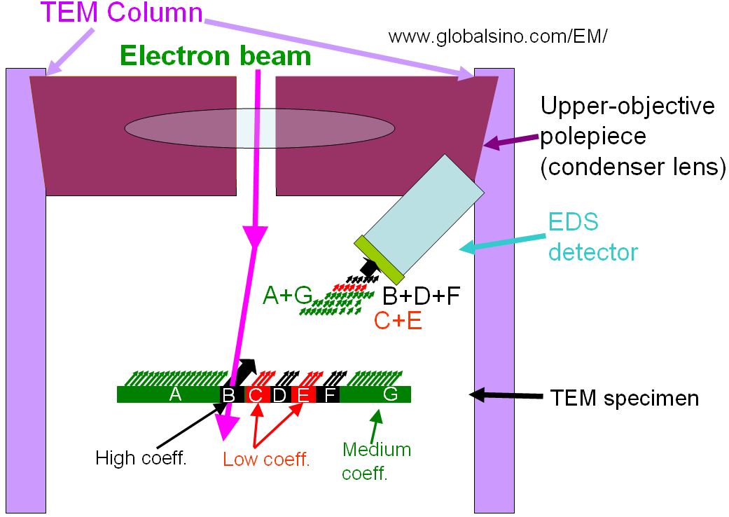
of beam irradiation and electron backscattering when the electron beam probes a single pixel on three different materials which have different degrees of backscattering coefficients. Generation of X-rays due to electron backscattering is mainly a function of backscattering coefficient of electrons, specimen thickness, and the area of the materials. For instance, the areas of regions B, C, D, E, and F are the same; however, because the backscattering coefficient of regions B, D and F is higher than that of regions C and E, more X-rays are generated and collected by EDS detector when the beam probes a pixel in regions B, D or F. On the other hand, even though regions A and G have lower backscattering coefficient than regions B, D and F, the materials in regions A and G still generate more background X-rays when the beam probes a pixel anywhere on the specimen since the total area of regions A and G is much larger.
Figure 3815a. (a) X-rays generated by backscattered electrons. Degrees of X-ray generations: (b) less X-rays generated from materials with a low backscattering coefficient, (c) medium X-rays generated from materials with a medium backscattering coefficient, and (c) more X-rays generated from materials with a high backscattering coefficient. The big arrows in (a-c) represent the X-rays generated by the direct beam irradiation. The numbers of small arrows indicate the degrees of X-ray generation. The three colors (black, green, and red) of the arrows represents the characteristic X-rays generated from the three different materials with different backscattering coefficients.
|
|