=================================================================================
The incident electron beam can be considered as made of a set of incident rays within an incident cone. In two-beam condition, the resulting pattern located in the back focal plane consists of two disks but not of two spots, namely the transmitted and hkl diffracted disks as shown in Figure 3890a (a). Given the strength of the objective lens is unchanged, when the defocus is changed from zero to Δh by adjusting the height of the TEM sample, the transmitted and diffracted beams in the diffraction pattern in the back focal plane will be changed from Figure 3890a (a) to (b). In this case, the diffraction spots in the image plane also move. Assuming the strengths of the other lenses in the TEM system are not changed, the diffraction pattern on the TEM screen or detector will be very different from the cases in Figure 3890a (a) to (b). If you are working on TEM-imaging mode, the TEM image will also be very different.
Figure 3890a. TEM optics under conditions of focused (a) and defocused (b) convergent incident electron beams.
Annular dark-field transmission electron microscopy (ADF-TEM) is widely used to evaluate the mass-thickness, atomic number and imaging of TEM samples. A simple ADF-aperture setup uses an annular objective aperture that acts as a central beam stop in the back focal plane of the objective lens [1 – 5] as shown in Figure 3890b. This aperture also blocks the outer electrons scattered at very high semiangles. Therefore, the central beam and all electrons scattered at very high semiangle are excluded from imaging. By optimizing the dimension of the inner and outer rings (~ 86 µm for the inner ring and ~200 µm for the outer ring in Figure 3890b), many applications can be obtained. The SEM (secondary electron microscopy) image in Figure 3890b (b) shows an annular aperture fabricated using focused-ion-beam (FIB) technique.
Figure 3890b. a) Schematic illustration of the column of a scanning transmission electron
microscope (STEM) system. b) An ADF aperture prepared using focused-ion-beam (FIB) technique.
For an ideal objective lens, the incident electron probe simply forms an Airy disc in the back focal plane of the lens. This disc is the Fourier transform of the uniformly illuminated condenser aperture.
Figure 3890c gives a very simplified illustration of how the incident electrons travel through the TEM column. r is the real space coordinates in the sample or image, u is the reciprocal space coordinates and θ is the scattering angle.
Figure 3890c. Simplified illustration of how an image is formed in a TEM column.
As shown in Figure 3890d, in TEM bright-field (BF) mode, an objective aperture is placed in the back focal plane of the objective lens which allows only the transmitted beam to pass. In this case, mass-thickness and diffraction contrast contribute to image formation, that is thick areas, areas with heavy atoms, and crystalline areas in most crystalline orientations appear in dark contrast. The mixed contrasts make the interpretation difficult.
Figure 3890d. TEM bright field (BF) mode.
Different from bright-field (BF) TEM imaging condition, in dark-field (DF) TEM imaging condition, as shown in Figure 3890e one or more diffracted electron beams are allowed to pass the objective aperture placed in the back focal plane of the objective lens while the transmitted electron beam is blocked by the aperture. In Figure 3890e (a) a smaller aperture is used to select a single diffracted beam only, while in Figure 3890e (b) a bigger aperture is used to select two diffracted beams.
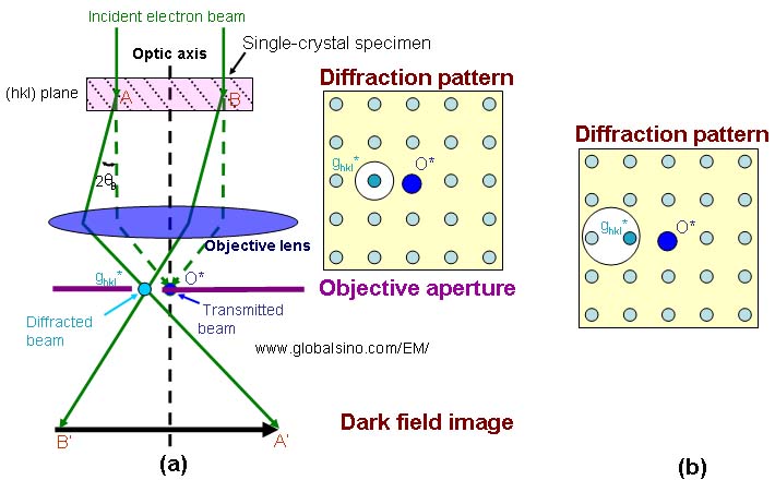
Figure 3890e. Dark-field (DF) TEM imaging conditions.
The white disks indicate objective apertures.
Figure 3890f shows the comparison of the lens conditions between TEM diffraction and TEM imaging modes. Those two modes are the basic modes in TEM operations. The difference between the two modes may only be the strength of the intermediate lens.
Figure 3890f. Comparison of the lens conditions between TEM diffraction and TEM imaging modes.
Figure 3890g (a) shows the principle of magnifying an image (Normal-Mag mode). A transmitted image of the specimen is first formed and magnified by the objective lens, and then is magnified further by two to four lenses, including an objective lens, intermediate lenses, and a projector lens. As shown in Figure 3890g (b), at extremely low magnification (e.g. used for survey of interest), the image is formed by the OM (objective-mini) lens, intermediate lenses, and projector lens. The Diff mode in Figure 3890g (c)presents an electron diffraction pattern. In the Normal-Mag mode, the focus of the 1st intermediate lens is adjusted to the image plane of the objective lens where a selected area aperture is located. However, in the Diff mode, the focus of the 1st intermediate lens is adjusted at the back focal plane of the objective lens. Table 3890 lists the status of the lenses and apertures in different operation modes.
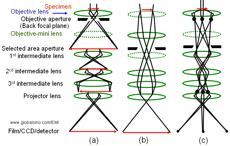
Figure 3890g. (a) Normal-Mag mode, (b) Low-Mag mode, and (c) Diff mode. The dashed-lenses are turned off in the relevant operation mode.
Table 3890. Status of the lenses and apertures in different operation modes*.
Lens |
|
|
|
|
On |
Off |
On |
Objective aperture (back focal plane)
|
Normally use |
Normally not use |
Normally not use |
|
Off |
On |
Off |
|
Normally not use |
Either use or not use |
Either use or not use |
Focus of 1st intermediate lens |
At the image plane of the objective lens |
- |
At the back focal plane of the objective lens |
|
On |
Off |
On |
|
On |
On |
On |
|
On |
On |
On |
|
On |
On |
On |
* "Normal-Mag mode" includes normal and high magnifications for HRTEM; "Low-Mag mode" includes very low magnifications, which is used for specimen survey; and "Diff mode" is for electron diffraction analysis. |
Figure 3890h shows the misalignment of an objective lens, where the off-axis electron beam enters the objective lens. For a specific lens setting, the object ABC forms an image A'B'C'. The image will be changed to A"B"C" (smaller than A'B'C') with a center (B' or B”) formed by the unchanged beam (BB' or BB”) if the objective lens setting is changed. In this case, the back focal plane of the objective lens is also changed. Furthermore, as shown in Figure 3890h (b) this change induces a rotation of the image because of the helical path of the electrons through the lens. This can happen, for instance, when the objective lens current is changed.
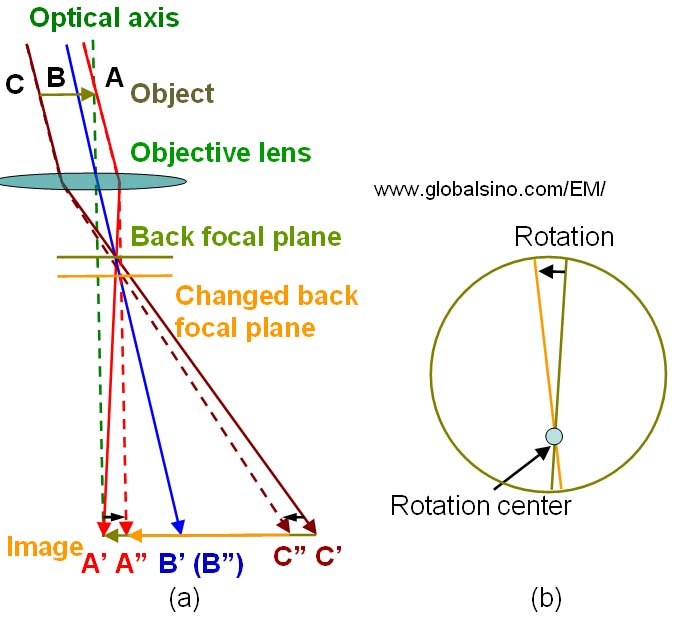
Figure 3890h. Misalignment of the objective lens: (a) Sweep of the image, and (b) Combination of sweep and rotation of the image on the viewing screen in the EM.
Figure 3890i shows the full view of of the practical double-sextupole Cs correctors for STEM and for TEM, respectively. The positions of the correctors with respect to the front and back focal planes for STEM and TEM, respectively, are also indicated.
Figure 3890i. Double-sextupole spherical aberration correctors for: (a) STEM and (b) TEM.
On the other hand, CBED also provides the diffraction patterns in the back focal plane of the objective lens.
To have a camera length exactly as labeled in the instrument, some key points need to be satisfied as follows:
i) The specimen should be placed exactly at the Eucentric height in the objective lens.
ii) A parallel electron beam should be employed.
iii) The focus of the objective lens should be exactly adjusted to the focus position.
iv) The focus of the first intermediate (with “Diff focus” knob) should be adjusted at the back focal plane of the objective lens.
[1] K. Heinemann, H. Poppa, Phys. Rev. Lett. 1972, 20, 122.
[2] Z. L. Wang, A. T. Fisher, Ultramicroscopy 1993, 43, 183.
[3] Z. L. Wang, Ultramicroscopy 1994, 53, 73.
[4] S. Bals, B. Kabius, M. Haider, V. Radmilovic, C. Kisielowski, Solid
State Commun. 2004, 130, 675.
[5] S. Bals, R. Kilaas, C. Kisielowski, Ultramicroscopy 2005, 104, 281.
|