Chapter/Index: Introduction | A | B | C | D | E | F | G | H | I | J | K | L | M | N | O | P | Q | R | S | T | U | V | W | X | Y | Z | Appendix
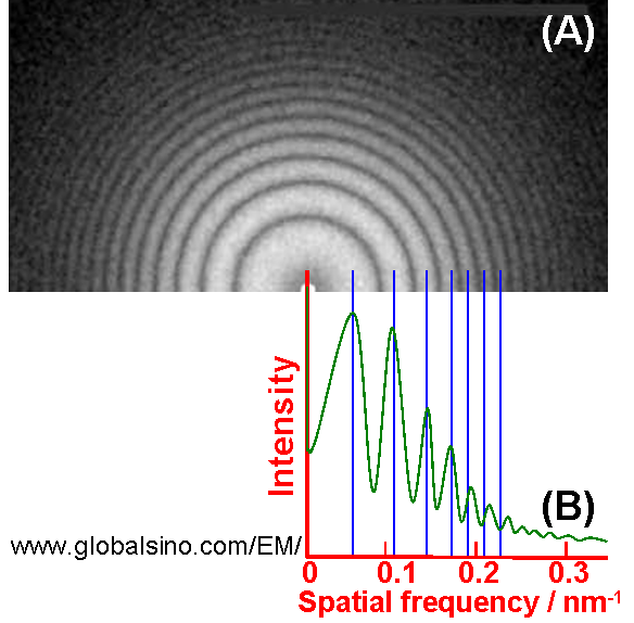
| A electron diffraction pattern of an amorphous specimen is typically a halo feature, while a diffraction pattern of a polycrystalline specimen shows well defined sharp Debye-Scherrer rings, indicating the presence of LRO in the specimen. Thon rings are a phenomenon revealed in the power spectra of micrographs by bright-field (BF) TEM (transmission electron microscopy) imaging. These rings can be explained as the effect of the contrast transfer function, which modulates the Fourier transform of the object in a defocus-dependent way. Figure 4189a (A) shows the power spectrum of a typical BF TEM image of amorphous carbon film presenting concentric Thon rings. Those white rings correspond to the contrast transfer maxima and the dark rings indicate spatial frequency bands without signal. Figure 4189a (B) shows the radial intensity of the power spectra. The astigmatism and defocus can affect the symmetry of the rings, limiting the spatial resolution of the microscope. Therefore, electron micrographs, especially HRTEM, are routinely inspected by optical diffraction before taking images for analysis.
Figure 4189a. (A) Power spectrum of typical bright-filed image of amorphous carbon film presenting
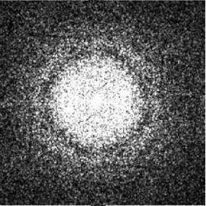
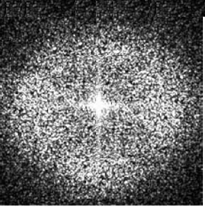
concentric Thon rings taken in TEM. (B) Radial intensity of the power spectra. Figure 4189b shows two Fourier transform patterns obtained from HRTEM images on amorphous carbon films at 0.5 Scherzer defocus and at Scherzer defocus, respectively.
Figure 4189b. Two Fourier transform patterns obtained from HRTEM images on
|