Chapter/Index: Introduction | A | B | C | D | E | F | G | H | I | J | K | L | M | N | O | P | Q | R | S | T | U | V | W | X | Y | Z | Appendix
|
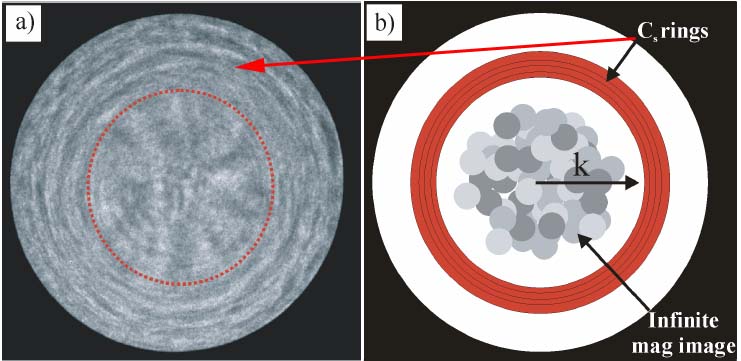
Figure 4259a (a) shows the coherent electron Ronchigram formed from an amorphous material. The interference pattern of the Ronchigram at the smooth center flashes randomly due to the small movements of the incident electron probe and specimen. If the sample is more than a few nm thick, the smooth region will be replaced by faint random mist because the top and bottom cannot be at infinite magnification at the same defocus. [1] Figure 4259a (b) shows a schematic illustration of the Ronchigram indicating the location of the rings caused by spherical aberration (Cs) and the shadow image inside the rings. The aperture size should be small enough in order to exclude these rings. However if a too small aperture is used the available high frequencies will not be included and the probe becomes diffraction limited. In practice, the probe-forming aperture marked by the red dotted circle in Figure 4259a (a) is just inside the consequence of the Cs rings.
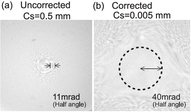
Figure 4259a (a) The coherent electron Ronchigram formed from an amorphous material, and (b) The rings caused by spherical aberration and the shadow image inside the rings. [1] Figure 4259b shows that an observed Ronchigram from an amorphous germanium TEM film showed a coherently converged angle > 40 mrad in half-angle when the Cs(spherical aberration)-corrector was turned on. This angle was much lager than that for the uncorrected beam.
Figure 4259b. Ronchigrams for the probe-forming lens system with a Cs-corrector (a) corrector off and (b) corrector on. [1] M. Weyland and D. A. Muller, Tuning the convergence angle for optimum STEM performance, FEI nanoSolutions, (2006) 24.
|