=================================================================================
Figure 4278a shows schematic illustration of the rotationally symmetric magnetic fields and the electron lenses. According to Newton’s law, the differential equations for the electron trajectories in the cylindrical coordinate system r, φ, z can be given by,
 (radial component) ------------------------ [4278a] (radial component) ------------------------ [4278a]
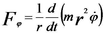 (circular component) ------------------------------- [4278b] (circular component) ------------------------------- [4278b]
 (longitudinal component) --------------------------------- [4278c] (longitudinal component) --------------------------------- [4278c]
The last term in Equation 4278a provides the centrifugal force.
By calculating the circular component in Equation 4278b in combination with Lorentz force, we can obtain that the trajectory for meridional rays in a meridional plane rotating behaves at an angular velocity,
 --------------------------------- [4278d] --------------------------------- [4278d]
This equation is known as the Larmor frequency that is half the cyclotron frequency of an electron on a circular trajectory.
For paraxial rays (small values of r), Equation 4278c can be re-written by  = 0, resulting in that vz is constant. = 0, resulting in that vz is constant.
Further calculation can help us to find,
 --------------------------------- [4278e] --------------------------------- [4278e]
where,
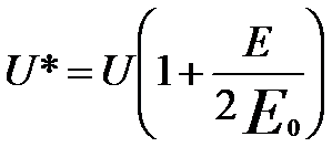 --------------------------------- [4278f] --------------------------------- [4278f]
Equation 4278e gives the trajectory r(z) in the meridional plane rotating
at the angular velocity ωL.
Figure 4278b shows the electron trajectories incident parallel to the axis for increasing values of lens strength (ω).
Here, ω is the strength parameter of the lens given by ω = (1+k2)1/2.
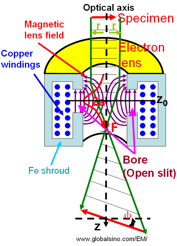
Figure 4278a. Schematic illustration of rotationally symmetric magnetic fields and electron lenses.
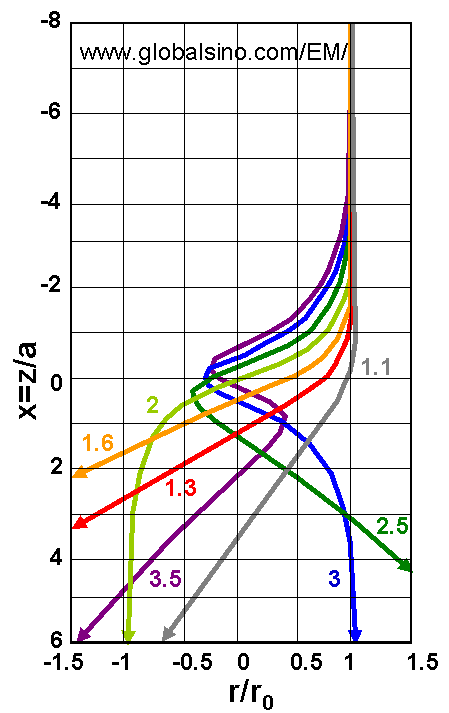
Figure 4278b. The electron trajectories incident parallel to the axis for increasing values of lens strength (ω). Adapted from [1]
In reality the electrons have helical trajectory in the lenses as shown in Figure 4278c. The electromagnetic lenses consist of windings of wire through which the electric current is applied. These configurations create a strong magnetic field where the incident electron beam must pass. The electrons follow a helical trajectory which converges at a fine focal point after they emerge from the lens. Here, the DC(direct current)-powered magnets behave similar to converging glass lenses in optical microscopes.
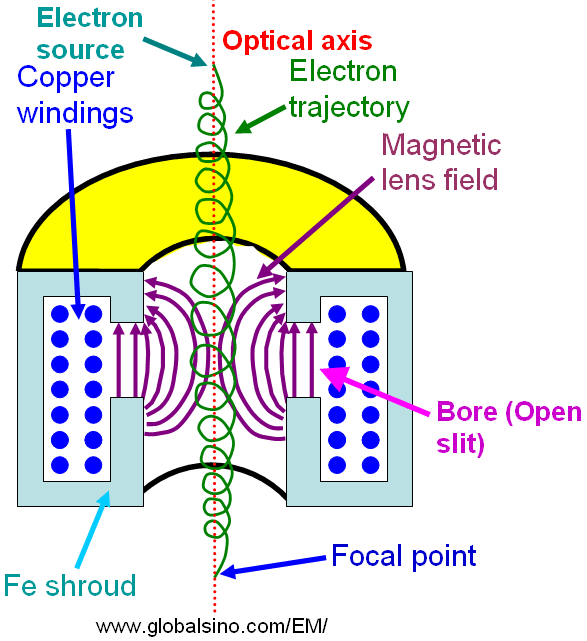
Figure 4278c. Schematic illustration of electrons passing through electromagnetic lenses.
[1] W. Glaser: Grundlagen der Elektronenoptik (Springer, Wien, 1952).
|
 (radial component) ------------------------ [4278a]
  (circular component) ------------------------------- [4278b]
 --------------------------------- [4278e]
 --------------------------------- [4278f]


