=================================================================================
Figure 4839a shows the schematic of low vacuum or environmental SEM systems. The primary electrons (PEs) from the electron gun enter the chamber from the high vacuum column via one or more pressure limiting aperture [1]. PEs scattered by gas molecules form a relatively delocalized electron ‘‘skirt’’ around the unscattered component of the electron beam [2-3].
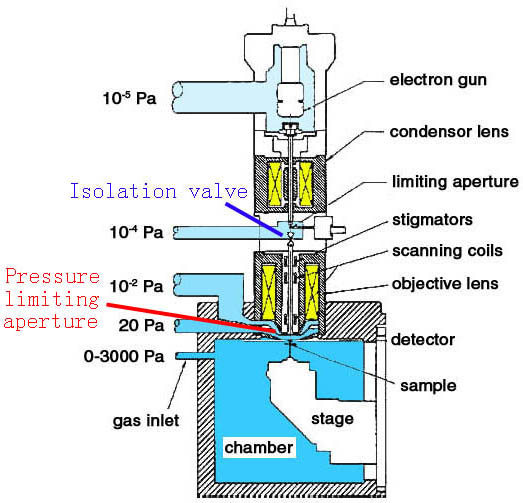
Figure 4839a. Schematic of low vacuum or environmental SEM systems.
Figure 4839b gives the schematic of a low vacuum SEM chamber. The PEs and electrons ejected from a sample are amplified in a gas ionization cascade produced by placing a positively biased electrode Ve (typically 50 - 600 V) into the sample chamber [4]. The net electron current arriving at the electrode of the GSED (gaseous secondary electron detector) ring is given by [5]
IGSED = Ib + [δ(1-Ω)gSE + ηgBSE](1-s)IPE ------------------------------------------------------ [4839]
IPE -- the primary beam current
Ib -- a
background offset generated
by gas amplification of PEs and electrons
ejected from the sample by skirt electrons
s -- the
fraction of PEs that form the skirt
δ -- the
secondary electron emission
yield
η -- the
backscattered electron emission
yield
gSE -- the secondary electron gas amplification factor
gBSE -- the
backscattered electron gas amplification factor
Ω -- the SE-ion recombination probability
g -- the gas gain as a function of the electric field in the space between the sample and the electrode (detector)
Figure 4839b. Schematic of a low vacuum SEM chamber. BSE = backscattered electron, SE = secondary electron,
ESE = environmental SE [6]
[1] G.D. Danilatos, Adv. Electron. Electron Phys. 71 (1988) 109.
[2] D.A. Moncrieff, P.R. Barker, V.N.E. Robinson, J. Phys. D 12 (1979) 481.
[3] A.N. Farley, J.S. Shah, J. Microsc. 158 (1990) 379.
[4] G.D. Danilatos, Adv. Electron. Electron Phys. 78 (1990) 1.
[5] M. Toth, M.R. Phillips, B.L. Thiel, A.M. Donald, J. Appl. Phys. 91 (2002) 4479.
[6] M. Toth, B.L. Thiel, A.M. Donald, Ultramicroscopy 94 (2003) 71–87
|