=================================================================================
Any robust and efficient tuning of a Cs corrector system employs software to characterize the lens aberrations and to use the obtained information to correct the aberrations prior to image recording. The commercial products today can essentially reduce Cs to zero, and even allow it to go negative. Two approaches are currently available to identify and measure the aberrations based on PC control:
i) Using the diffraction information shown in the ring-like patterns below each phase contrast image that are acquired with the incident beam aligned along the optic axis. By tilting the beam off the optic axis, lens aberrations become apparent in the Fourier transforms of phase contrast images. A set of such patterns obtained at various beam tilts around the optic axis is called a "Zemlin tableaux". The distortions of the circular patterns in the Zemlin tableaux are used for characterizing the aberration. This method is well-suited for HRTEM imaging.
ii) Using "Ronchigrams" somewhat similar to convergent beam electron diffraction. However, unlike the CBED pattern, a Ronchigram is obtained using a large aperture angle, so the diffraction disks overlap considerably. Phase interferences of the different beams occur in the Ronchigram and vary with focus. In this method, a set of Ronchigrams acquired at different focus settings can characterize the lens aberrations.
Zemlin tableaux are not only applied to aberration correction but also used in routine coma-free alignment. The basis of this method of coma-free alignment is to generate tableaux of FFT patterns with a systematic beam tilt, similar to the method applied by Zemlin et al. [2]. As an example, Figure 1910a (A) shows a five-panel FFT tableau obtained from five TEM images after the alignment of the microscope but without coma-free alignment. The center panel shows the FFT pattern of the image obtained without any additional beam tilt, while the panels on the four corners show the FFT patterns of the images recorded after applying additional beam tilts of ± 5 mrad in the x and y directions, respectively. The beam direction in the central panel is not parallel to the coma-free axis, indicated by the fact that the astigmatism is slightly different for “plus” versus “minus” tilt angles. Therefore, a coma-free alignment was done by applying small beam tilts. After a small beam tilt, a tableau of FFT patterns similar to that presented in Figure 1910a (A) is recorded and compared. However, in most cases, the coma-free alignment cannot be completed by a single, small beam tilt, and thus this process is continued until the tableau is made as symmetric in appearance as possible. Figure 1910a (B) shows the FFT tableau after performing the entire process of coma-free alignment. In this tableau, the defocus and astigmatism for all the four corner panels are very similar and the tableau is symmetrical in both x and y directions.
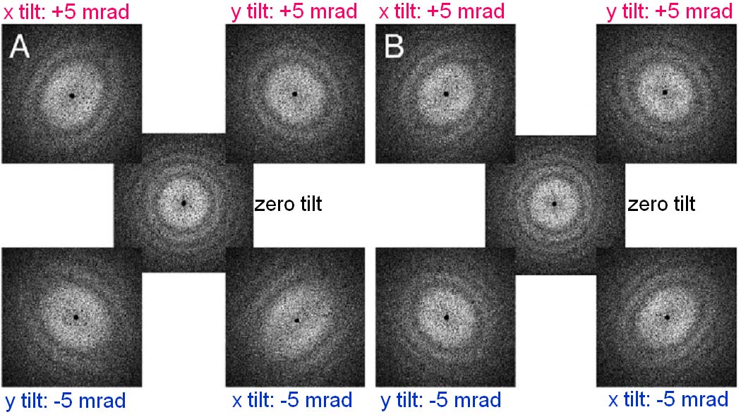
Figure 1910a. Tableaux of FFT patterns obtained before (A) and after (B) coma-free alignments.
Adapted from [1]
Figure 1910b shows the schematic comparison of Zemlin (diffractogram)-tableau characteristics for the axial aberrations up to third orders. First-order aberration (e.g. defocus and twofold astigmatism, A1) shows the elliptical distortion even without electron beam tilting because the impact of first-order aberrations does not depend on the tilt angle. For the aberrations of higher orders (n≥2), such as second-order axial coma B2, three-fold astigmatism A2, third-order spherical aberration C3 (>0), third-order star aberration S3 and four-fold astigmatism A3, there is no elliptical distortion observable for the un-tilted case. In these cases, only at illumination tilts the characteristic distortion due to the aberrations becomes discernible. Note that the higher-order aberrations have equal symmetries to the ones in Figure 1910b as discussed in page3740.
Figure 1910b. Schematic representation of Zemlin (diffractogram)-tableau characteristics for the axial aberrations up to third order.
[1] Robert M. Glaeser, Dieter Typke, Peter. Tiemeijer, James Pulokas, Anchi Cheng, Precise beam-tilt alignment and collimation are required to minimize the
phase error associated with coma in high-resolution cryo-EM, Journal of Structural Biology 174 (2011) 1–10.
[2] Zemlin, F., Weiss, K., Schiske, P., Kunath, W., Herrmann, K.H., Coma-free
alignment of high-resolution electron-microscopes with aid of optical
diffractograms. Ultramicroscopy 3, (1978) 49–60.
|