Chapter/Index: Introduction | A | B | C | D | E | F | G | H | I | J | K | L | M | N | O | P | Q | R | S | T | U | V | W | X | Y | Z | Appendix
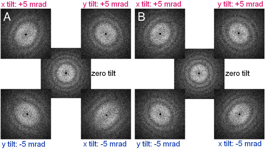
| A specific tilt angle of the electron beam can be found such that the image coma becomes negligible for a chosen point in the TEM specimen. In this case, the position of the unscattered (transmitted) electron beam, focused in the back focal plane of the objective lens, lies on the optical axis. More accurately speaking, one refers to this axis as the coma-free axis for the given point in the specimen, but one normally refers to the axis defined by coma-free alignment as being optical axis. In conventional microscopes with round lenses and without appropriate aberration correctors the axial coma can only be compensated by the so-called coma-free alignment, in which the electron beam axis is aligned until the axial coma generated by the combination of the beam displacement with the spherical aberration of the round lenses disappears in the image. This alignment disturbs the general alignment of the electron-optical column. Coma-free alignment is almost influenced only by the objective lens, while the voltage-center is influenced by the whole lens system in the microscope. In many commercial TEMs, both coma-free and voltage-centering alignments use the same beam deflectors above the objective lens for adjusting the direction of incident beam, the coma-free alignment is achievable only at the expense of the voltage-center alignment, and vice versa. However, it was also proposed [3] that the coma-free alignment can be obtained by using beam deflectors above the objective lens, while the voltage-centering alignment is adjusted by beam deflectors below the objective lens. In conventional TEMs, aberration correction was limited from difficult finding the coma-free axis of the objective lens by intentionally using an illumination tilt, followed by eliminating twofold astigmatism with the objective lens stigmators. In a microscopes with correctors for coma corrections, the axial coma can be corrected directly, e.g. by means of hexapoles in the inner multipole elements without disturbing the general alignment of the column: The pattern is defocused in one direction and the hexapole in the same element is changed until the intensity distribution in the aberration pattern becomes symmetric in the defocus. Note that the Cs and coma corrections cannot further improve the resolution when reaching 0.5 Å at voltages ≤ 200 kV due to chromatic aberration. The main advantage of using a Ronchigram, e.g. in STEM mode, is that the coma-free axis is directly visible. By wobbling the condenser lens excitation and then the microscope high tension, the alignment of the illumination electron beam in STEM mode can be very accurately checked. If there is a misalignment of the beam between condenser and objective lenses, there will be a periodic translation of Ronchigram features when the wobbling takes place. This misalignment can be corrected by using the condenser alignment coils (CTEM bright tilt in JEOL systems) so that the features only oscillate in and out symmetrically about the coma-free axis. Various coma-free alignment procedures in TEM imaging have been developed: In Cs-correctors based on double-hexapoles, between the objective lens and the first hexapole plane, there is an additional transfer doublet of round lenses in order to deliver the coma-free point of the objective lens into the plane of the first hexapole. In Cs-corrected EMs, due to the absence of spherical aberration it is not possible anymore to correct the residual axial coma by tilting the illumination beam. In this case an appropriate coma compensator is needed to eliminate the coma. Furthermore, a small misalignment of the direction of the incident electron beam introduces wave aberrations and thus affects the quality of the images [ 1,2] so that coma-free alignment is essential for HRTEM. In some microscopes (e.g. FEI TEMs), the procedure of the coma-free alignment is very simple under the help of computer interface: A procedure to obtain accurate coma-free alignment is to generate tableaux of FFT patterns with a systematic beam tilt, similar to the method applied by Zemlin et al. [5]. As an example, Figure 4238 (A) shows a five-panel FFT tableau obtained from five TEM images after the alignment of the microscope but without coma-free alignment. The center panel shows the FFT pattern of the image obtained without any additional beam tilt, while the panels on the four corners show the FFT patterns of the images recorded after applying additional beam tilts of ± 5 mrad in the x and y directions, respectively. The beam direction in the central panel is not parallel to the coma-free axis, indicated by the fact that the astigmatism is slightly different for “plus” versus “minus” tilt angles. Therefore, a coma-free alignment was done by applying small beam tilts. After a small beam tilt, a tableau of FFT patterns similar to that presented in Figure 4238 (A) is recorded and compared. However, in most cases, the coma-free alignment cannot be completed by a single, small beam tilt, and thus this process is continued until the tableau is made as symmetric in appearance as possible. Figure 4238 (B) shows the FFT tableau after performing the entire process of coma-free alignment. In this tableau, the defocus and astigmatism for all the four corner panels are very similar and the tableau is symmetrical in both x and y directions.
Figure 4238. Tableaux of FFT patterns obtained before (A) and after (B) coma-free alignments. Adapted from [4]
[1] K. Ishizuka and S. Iijima, Proc. 39th EMSA Annual Meeting,
Atlanta (1981) 96.
[2] D.J. Smith. W.O. Saxton, M.A. O’Keefe, G.J. Wood and W.M. Stobbs. Ultramicroscopy I1 (1983) 263. [3] T. Yanaka. K. Shirota, A. Yonezawa and Y. Arai, in: Proc. 8th Int. Cong. on Electron Microscopy. Canberra. 1974. Vol. I. p. 128. [4] Robert M. Glaeser, Dieter Typke, Peter. Tiemeijer, James Pulokas, Anchi Cheng, Precise beam-tilt alignment and collimation are required to minimize the phase error associated with coma in high-resolution cryo-EM, Journal of Structural Biology 174 (2011) 1–10. [5] Zemlin, F., Weiss, K., Schiske, P., Kunath, W., Herrmann, K.H., Coma-free alignment of high-resolution electron-microscopes with aid of optical diffractograms. Ultramicroscopy 3, (1978) 49–60.
|