|
This book (Practical Electron Microscopy and Database) is a reference for TEM and SEM students, operators, engineers, technicians, managers, and researchers.
|
=================================================================================
Figure 1962a shows the structure of the electron probe-forming system in STEM mode in JEOL JEM-2010F TEMs. A cross-over is formed between the two condenser lenses (C1 and C2) by employing near-maximum excitation in the C1 lens, resulting in a large source de-magnification.
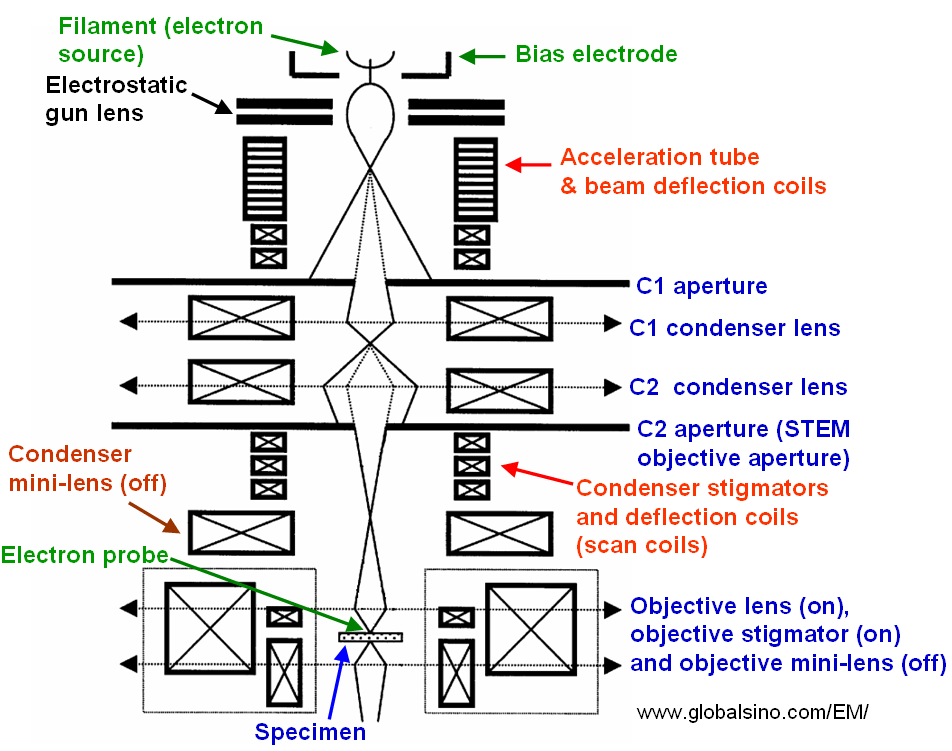
Figure 1962a. Schematic illustration of the probe-forming electron optics in STEM mode in JEOL JEM-2010F TEMs.
For convenience of microscope operation, we need to consider the coupling between the high voltage accelerator and the condenser system. The input electron beam to the condenser system should not vary significantly as the working voltage is changed. The position of the crossover of the beam leaving the accelerator especially should not move greatly along the axis.
Figure 1962b shows typical Ronchigrams taken at the edge of an amorphous carbon film. At defoci (defined by z-height), there is a distance between the electron cross-over and the point on the specimen along the optic axis. At large underfocus, electron rays at all angles cross the optic axis after the specimen and it shows a shadow image of the specimen edge. At small underfocus, low-angle rays cross the optic axis after the specimen, while high-angle rays cross before the specimen due to spherical aberration. Therefore, the shadow image changes in magnification as a function of the angle. The low-angle asymmetry indicates the presence of astigmatism. At Gaussian focus, the lowest-angle rays cross the axis at the specimen, while higher-angle rays cross before the specimen due to the spherical aberration. The coma free axis is defined at this focus and all alignment and positioning of detectors and apertures can be performed with respect to the low-angle “disk”. Defocus and spherical aberration can effectively cancel each other at those lowest angles. Axial astigmatism can be accurately corrected by using the stigmator coils, resulting in circularly symmetric Ronchigram features. At overfocus, rays at all angles cross the axis before the specimen.
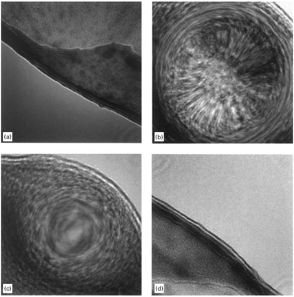
Figure 1962b. Ronchigrams of a thin amorphous carbon (C) film at: (a) Large underfocus, (b) Small underfocus, (c) Gaussian focus, and (d) Overfocus.
[1]
[1] E.M. James, N.D. Browning, Practical aspects of atomic resolution imaging and analysis in STEM, Ultramicroscopy 78 (1999) 125-139.
|