Chapter/Index: Introduction | A | B | C | D | E | F | G | H | I | J | K | L | M | N | O | P | Q | R | S | T | U | V | W | X | Y | Z | Appendix
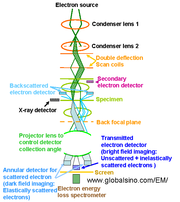
| The schematics in Figure 4536a shows the electron optical column in a modern analytical electron microscope operated in STEM mode.
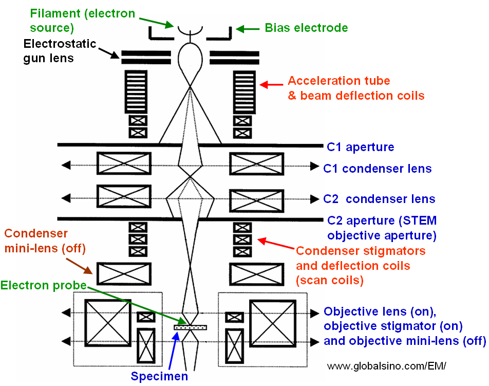
Figure 4536a. Schematics of the electron optical column in a modern In TEM systems, the first condenser and final projector lenses have short focal length and their designs are similar to that of the objective lens. However, the second condenser and the other projector lenses may be much weaker. In most modern, practical TEMs/STEMs, the gun lens is used to position the first crossover in relation to the beam-defining aperture (normally the C2 aperture). The crossover locates high above the aperture with a strong gun lens, while the crossover is close to the aperture with a weak gun lens. Both the beam current and aberrations on the beam are higher for the latter case. Therefore, when small, intense and low-aberration electron beams are needed, e.g. for diffraction in TEM and analytical STEM, a strong gun lens is selected; while a weak gun lens is selected when high probe currents are needed (e.g. TEM imaging). In the TEM mode, the beam is spreaded, therefore, the aberrations do not significantly affect the small imaging area. In STEM, there is only a condenser system, which is a lens used to form a fine probe. Sometimes this lens is also called objective lens. The correction of the spherical aberration of the pre-field lens is much cheaper comparing with post-field corrections. The main advantage of such correction is to reduce the beam tails so that a fine beam can be positioned at a specified column of atoms and does not spread its intensity into neighboring columns significantly. This tail spilling is critical for high resolution Z-contrast (HAADF) imaging and EELS analysis. In CTEM (conventional transmission electron microscopy) the condenser lenses can be used to form a broad parallel beam on the sample. Figure 4536b shows the structure of the electron probe-forming system in STEM mode in JEOL JEM-2010F TEMs. A setup, consisting of electrostatic gun lens and twin condenser lens system, controls the de-magnification of the Schottky field emission source. Compared with the cold field emitter, the Schottky electron source has a much larger emission area. Each element of the electron source can be assumed to emit electrons incoherently and thus results in an incoherent broadening of the probe [1]. A large de-magnification factor between the source and probe reduces this probe-broadening effect. In addition, the beam current decreases due to the probe-forming aperture. A cross-over is formed between the two condenser lenses (C1 and C2) by employing near-maximum excitation in the C1 lens, resulting in a large source de-magnification. The C2 lens and the gun lens are used to tune the probe coherence further by setting the probe size. In the STEM mode, both condenser and objective mini-lenses are tuned off.
Figure 4536c shows the TF20 Tecnai G2 200kV TEM (FEI).
For convenience of microscope operation, we need to consider the coupling between the high voltage accelerator and the condenser system. The input electron beam to the condenser system should not vary significantly as the working voltage is changed. The position of the crossover of the beam leaving the accelerator especially should not move greatly along the axis. In order to optimize the acquisition of holograms, in many cases, the microscopes need to be re-configured. For instance, Cooper et al. [2] turned off the probe corrector in their FEG FEI Titan microscope even though it had been installed. Both the objective lens and third condenser lens were turned off, and a Lorentz lens was used in order to extend the holographic field of view to 1500 x 700 nm2. We need to recalibrate the condenser lens adjustment from the FilterControl software if the EEL specimen illumination changes when the spectrum offset is changed. In TEM mode, the beam size is determined by the current of the 1st condenser lens (C1), and is affected by the convergence angle that is controlled mainly by the size of the C2 aperture and further adjusted by the objective lens prefield (or condenser mini-lenses). Note that artifacts can be induced by misalignment of condenser aperture.
[1] J.M. Cowley, Image contrast in transmission scanning
electron microscopy, Appl. Phys. Lett. 15 (1969) 58-60.
|