=================================================================================
Defect degradation in LEDs (light emitting devices) is dominated by the motion of dislocations in the active region with the creation of the so-called dark-line defects (DLDs). The DLDs are line defects along the [100] and [010] directions that appear during device operation. Similar to dark patches, DLDs form from pre-existing defects.
Figure 2106a shows an example of cathodoluminescence (CL) images. This image was taken from a ZnSe/GaAs heterostructure. The dark-line defects (DLDs) formed primarily along (100) directions ([100] and [010]) in the area (labeled A) photodegraded by an argon laser. Some DLDs marked by arrowheads are misoriented by 5 to 25 degrees from the <100> directions. "M" in the figure marks a misfit dislocation.
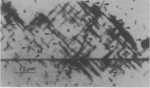
Figure 2106a. Cathodoluminescence (CL) image taken from a ZnSe/GaAs heterostructure. Adapted from [1]
Figure 2106b shows a TEM (-220) bright field image taken from a photo-degraded CdxZnl-xSe/ZnSxSel-x heterostructure. This figure presents extended networks of dislocation tangles along the <100> directions corresponding to the two DLDs. The DLDs consist of extended dislocation loops. A small faulted defect labeled b was blocked by a large stacking fault labeled T during photodegradation. Along the trace of the faulted defect, very small dislocation loops (marked by arrowheads) were formed.
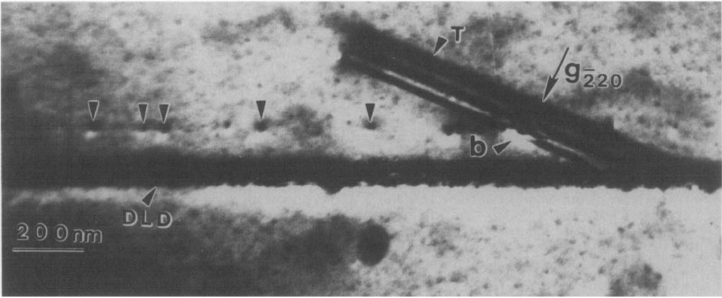
Figure 2106b. A TEM (-220) bright field image taken from a photo-degraded CdxZnl-xSe/ZnSxSel-x heterostructure. [1]
[1] L. Salamanca-Riba and L.H. Kuo, Observation of [100] and [010] Dark Line Defects in Optically Degraded ZnSSe-Based LEDs by Transmission Electron Microscopy, Journal of Electronic Materials, 25 (2) (1996) 239.
|