If the FilterControl software in the GIF (Gatan Imaging Filter) system can not recognize the hardware, the following steps need to be verified in trouble shooting process:
i) The Power Supply and Gatan Instrumentation Bin are turned on.
ii) The Gatan Instrumentation Bin (GIB) and the Gatan FilterControl computer are correctly connected each other.
For both GIF imaging and spectrum acquisition, we need to make sure:
i) The controllers (e.g. multi-scan camera controllers) are turned on.
ii) A suitably intense electron beam is placed in the center of the GIF camera. In this case, we also need to verify that the electron beam is not deflected out of the center of the GIF camera when the viewing screen is raised.
iii) Make sure the GIF gate valve is not stuck in the closed position. A control line for the gate valve should have a black label, while the other one a red label. When the black line is pressurized the gate valve should be open, when the red line is pressurized the gate valve should be closed.
iv) The Primary Energy in the FilterControl software is set to the operating energy of the TEM.
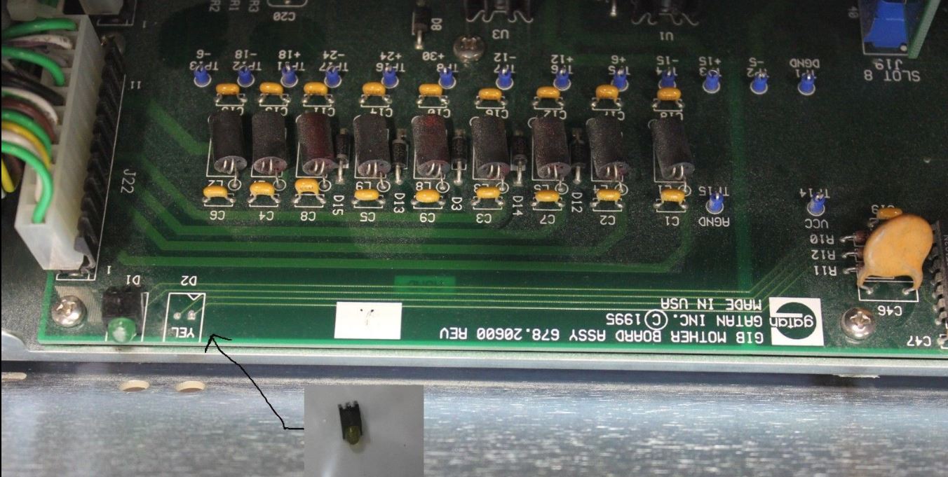
v) Check the communication between the FilterControl software and the Gatan Instrumentation Bin (GIB). If the communication is correct, the yellow LED on the front panel of the GIB should be on or flashing.
vi) The Drift Tube Voltage is turned off or set to 0; otherwise, the image or spectrum can be too weak to be visible.
If the Drift Tube Offset in GIF system does not work, then we need to check:
i) The Drift Tube Offset is turned on in the FilterControl software.
ii) The connection between the Gatan Instrumentation Bin (GIB) and the GIF is correct. The corresponding cable is black and has a high voltage BNC connector (see Figure 3330a) on both sides.
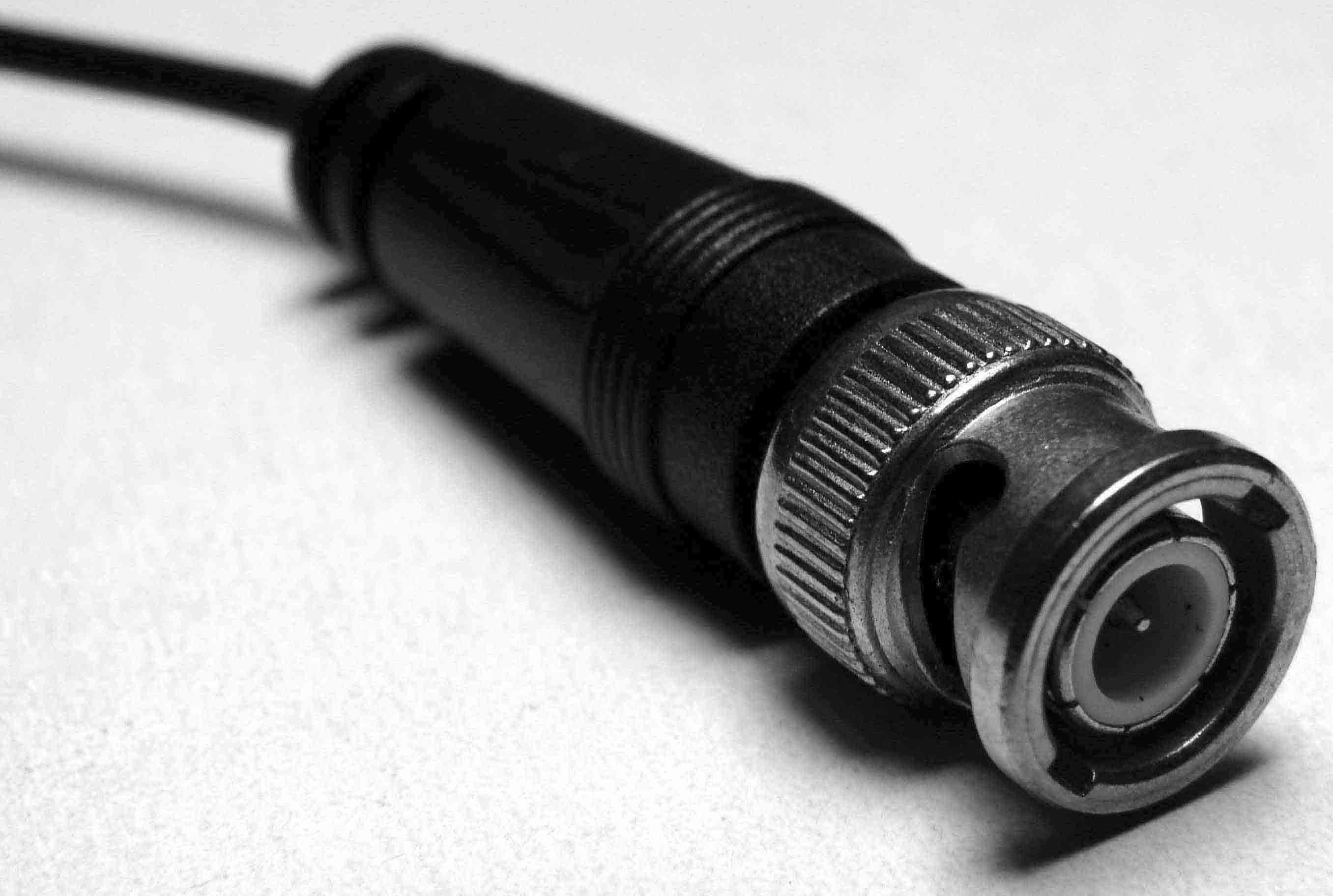
Figure 3330a. BNC connector.
If the EELS Energy Offset does not work, we need to check:
i) The Spectrum Offset is turned on in the FilterControl software.
ii) The connection between the GIB and the TEM HT electronics is correct. The corresponding cable is a thin coaxial cable coming from a D-SUB 44 connector at the GIB side.
In a GIF system, if the energy-selecting slit does not move in or out, then we need to check:
i) The presence of pressurized air.
ii) The pneumatic connections.
iii) There should be puffs of air coming from the GIB when the energy-selecting slit is moved in and out in the FilterControl software.
iv) Apply a high pressure (≤ 100 N/cm2) to the white slit control hose going into the GIF to loose the o-rings if the GIF has not been used for a long time because the o-rings may stick.
If the pneumatic aperture in GIF system does not work, then we need to check:
i) The presence of pressurized air.
ii) The pneumatic connections.
iii) There should be puffs of air escaping from the GIB when the aperture size in the FilterControl software is changed. In this case, the electronics controlling the pneumatics is working.
iv) Apply a high pressure (≤ 100 N/cm2) to the colored hoses coming from the aperture mechanism to loose the o-rings if the GIF has not been used for a long time because the o-rings may stick.
If the GIF stops working some time after it is turned on, then we need to do the troubleshooting as follows:
i) The GIF lenses may be or had been overheating so that the protection circuitry shut the lenses off. In this case, we need to check the water cooling. The flow indicator should be set to 0.05 gallons (0.19 liters) per minute. Furthermore, to verify that the water-flow indicator is not stuck at a reading, we can adjust the regulator valve to see if the flow rate changes or not.
ii) The fan in the GIB is running.
iii) Once we made sure the cooling is back to working correctly, the DigitalMicrograph interface (or plus the PC) needs to be restarted in order to turn the lenses back on.
iv) Measure the power supply voltages at the test points either on the back or inside the GIB. They should be within 10% of the values listed in the GIF user manual.
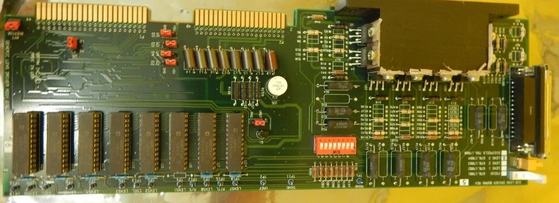
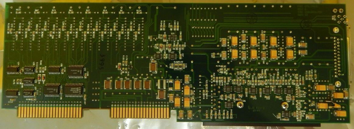
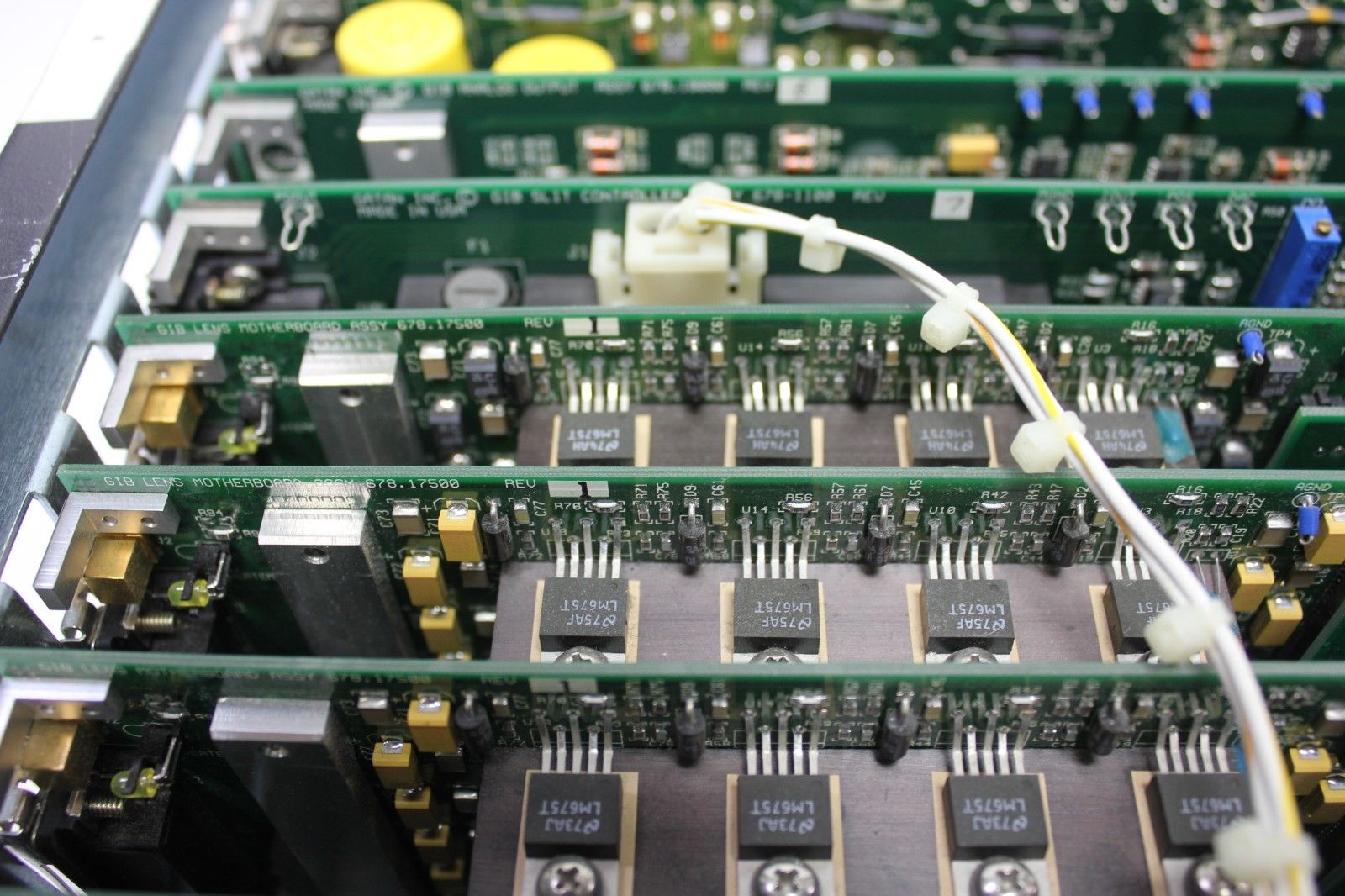
Figure 3330b shows a Gatan 678-17004 GIB Lens Driver LENS 3 PCB Card Rev. 5 which had been used in JEOL JEM-2010F.
| Figure 3330b. A Gatan 678-17004 GIB Lens Driver LENS 3 PCB Card Rev. 5: (a) Front side and (b) Back side. [1] |
|
(a) |
|
(b) |
|
(c) |
|
(d) |
|
(e) |
|
(f) |
|
(g) |
|
(h) |
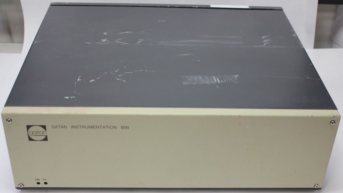
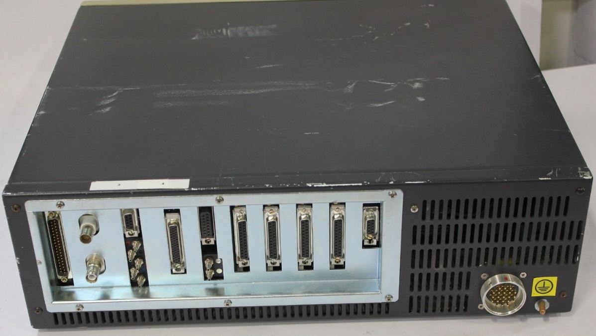
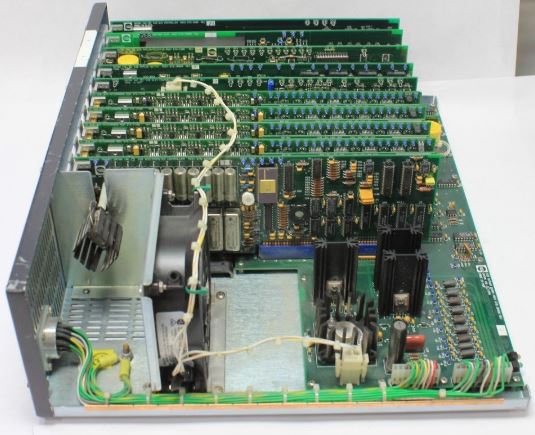
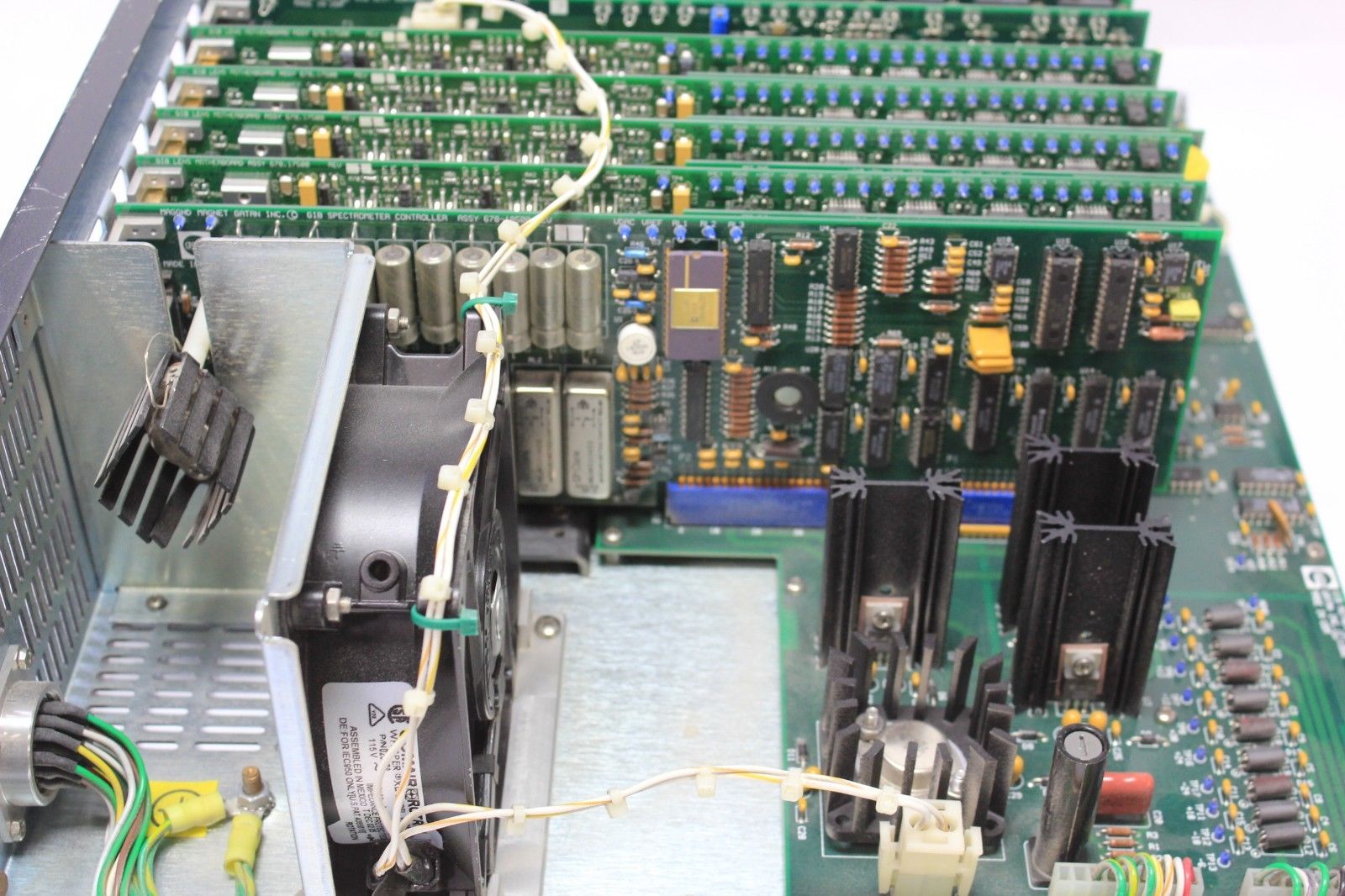
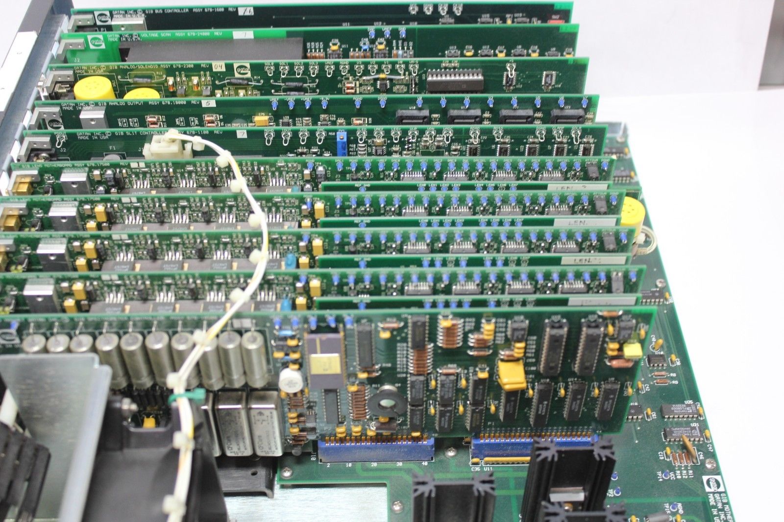
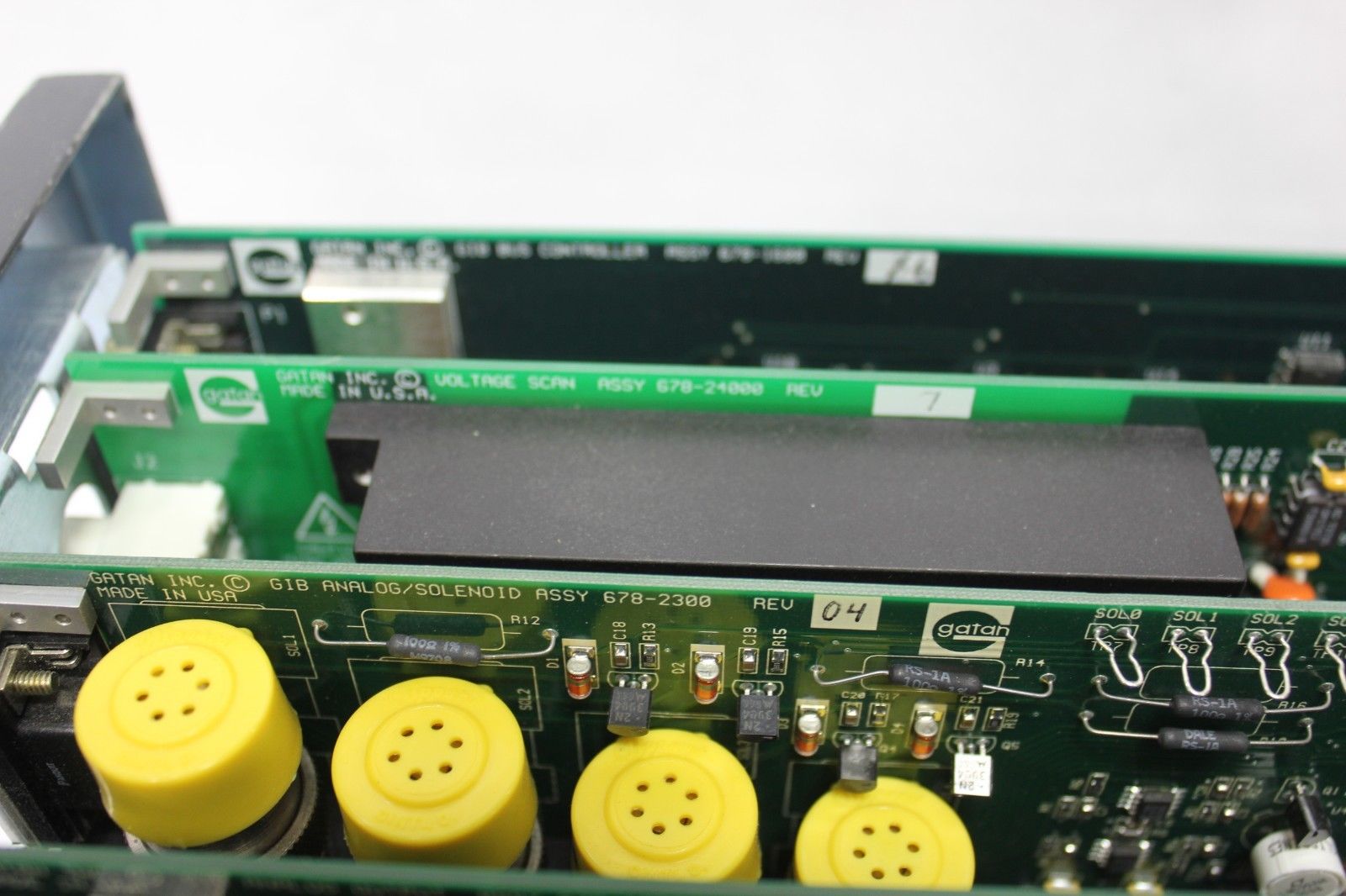
Figure 3330c. Gatan Instrumentation Bin (GIB). [1] |
[1] www.ebay.com.
|