=================================================================================
Energy dispersion can be calibrated using a drift tube in the magnetic sector. Figure 3943a shows the schematic illustration of a GIF (Gatan Imaging Filter) camera. The drift tube in the GIF system is also indicated in the figure. In DualEELS mode, the maximum ΔE in energy with the standard drift tube is 1,000 eV from the start of the first spectrum to the start of the second spectrum. However, the maximum ΔE with the fast drift tube 963.U4 is 2,000 eV.
Figure 3943a. Schematic illustration of a GIF (Gatan Imaging Filter) camera. Adapted from [1]
For both GIF imaging and spectrum acquisition, we need to make sure:
i) The controllers (e.g. multi-scan camera controllers) are turned on.
ii) A suitably intense electron beam is placed in the center of the GIF camera. In this case, we also need to verify that the electron beam is not deflected out of the center of the GIF camera when the viewing screen is raised.
iii) Make sure the GIF gate valve is not stuck in the closed position. A control line for the gate valve should have a black label, while the other one a red label. When the black line is pressurized the gate valve should be open, when the red line is pressurized the gate valve should be closed.
iv) The Primary Energy in the FilterControl software is set to the operating energy of the TEM.
v) Check the communication between the FilterControl software and the Gatan Instrumentation Bin (GIB). If the communication is correct, the yellow LED on the front panel of the GIB should be on or flashing.
vi) The Drift Tube Voltage is turned off or set to 0; otherwise, the image or spectrum can be too weak to be visible.
If the Drift Tube Offset in GIF system does not work, then we need to check:
i) The Drift Tube Offset is turned on in the FilterControl software.
ii) The connection between the Gatan Instrumentation Bin (GIB) and the GIF is correct. The corresponding cable is black and has a high voltage BNC connector (see Figure 3943b) on both sides.
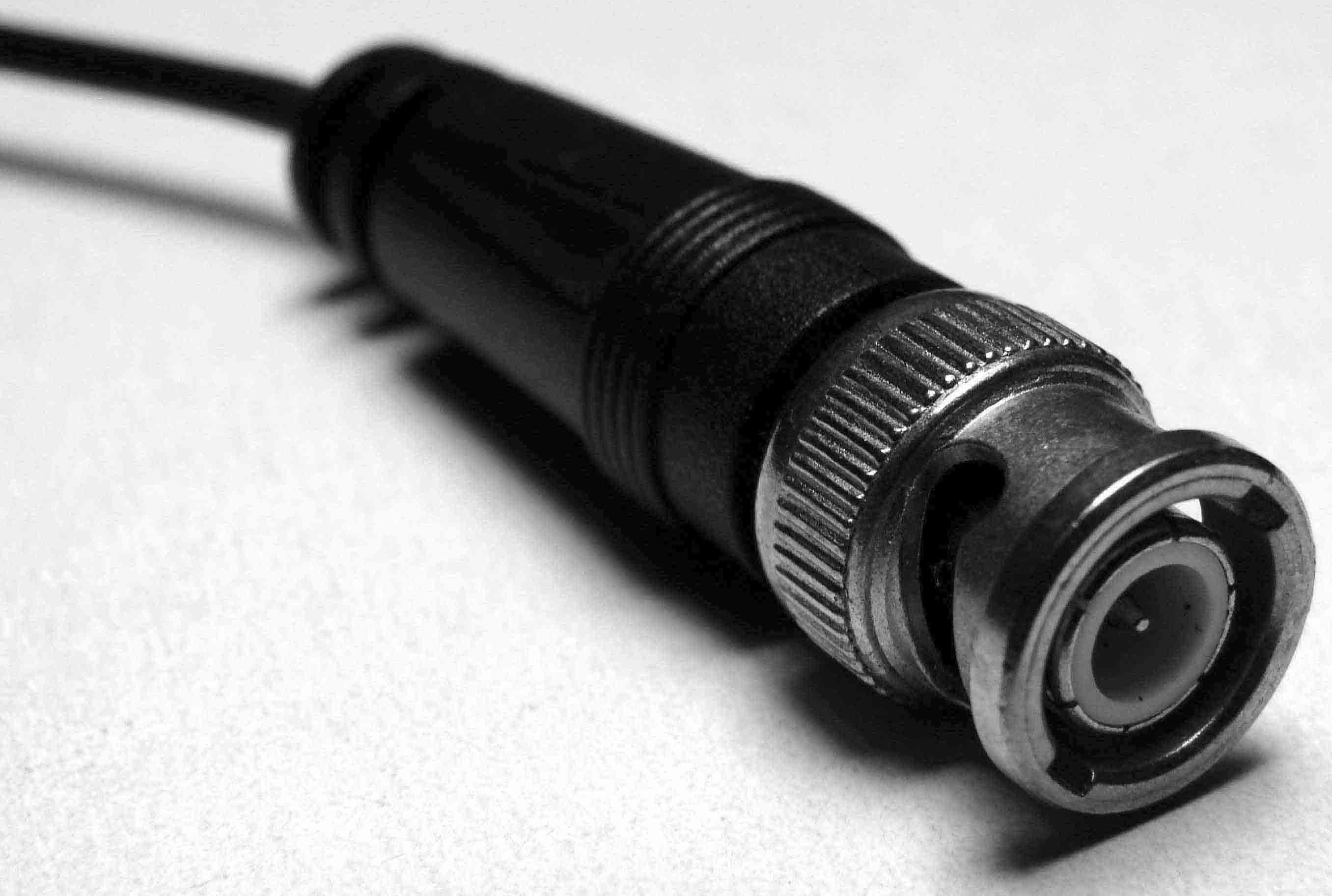
Figure 3943b. BNC connector.
Ideally, the detector channel of the zero-loss peak should be calibrated to the voltage offset applied to the spectrometer drift tube. However, it is not unusual that the energy stability is poor or there are spectral shifts due to magnetic fields so that the energy calibration is not reliable.
[1] http://www.gatan.com/.
|