=================================================================================
Figure 3667a shows the schematic illustration of formed wavefront due to the aberration coefficient C1,2 (or A1). The notations are described elsewhere.
Figure 3667a. Schematic illustration of formed wavefront due to aberration coefficient C1,2.
The aberration coefficient C1,2 brings the incoming wavefront of the electron rays traveling at different azimuths to different focus points as shown in Figure 3667b, which is simply two-fold axial astigmatism.
Figure 3667b. Schematic illustration of C1,2 astigmatism process.
There are mainly two steps to correct the astigmatisms in TEMs:
i) Correct the astigmatisms of the diffraction (inter-mediate, IL) and condenser (CL) lenses. Before the astigmatism correction for objective lens (OL) , the IL and CL astigmatisms should be corrected. The CL astigmatism must especially be corrected (without objective aperture) to ensure the proper correction of the OL astigmatism.
ii) Correct the OL astigmatism.
The Fresnel fringes in TEM images are affected by astigmatism of objective lens (OL). If the objective lens field is astigmatic (namely, not cylindrically symmetric), the focus will be different along different directions. For instance, those asymmetric Fresnel fringes present around the edge of a round hole in carbon (C) film. In this case, the fringes will disappear at some points before others. To correct the OL astigmatism, it is the best to find a small hole in the C film and then correct the OL astigmatism by making the Fresnel fringes symmetric. This lens for the correction function is called objective astigmator that is adjusted until the fringe is uniform around the hole and disappears uniformly when approaching focus. Note that this adjustment is always performed at the highest possible magnification using the binocular to view the image. Anticontaminator is often used to minimize contamination which increases the thickness of the film and thus makes the observation of the fringe more difficult.
Figure 3667c shows the change of Ronchigram taken at overfocus of 50 nm during C1,2 (A1) correction. The characteristic feature of the aberration marked by white broken lines disappeared after the aberration correction.
Figure 3667c. Change of Ronchigram taken at overfocus of 50 nm during C1,2 (A1) correction. Adapted from [1]
The changes of A1 and B2 from underfocus (UF) to overfocus (OF) are shown in Figure 3667d. At focus (F), the probed area is the smallest and the image blows-up to "infinity" magnification, while the images reverses from UF to OF.
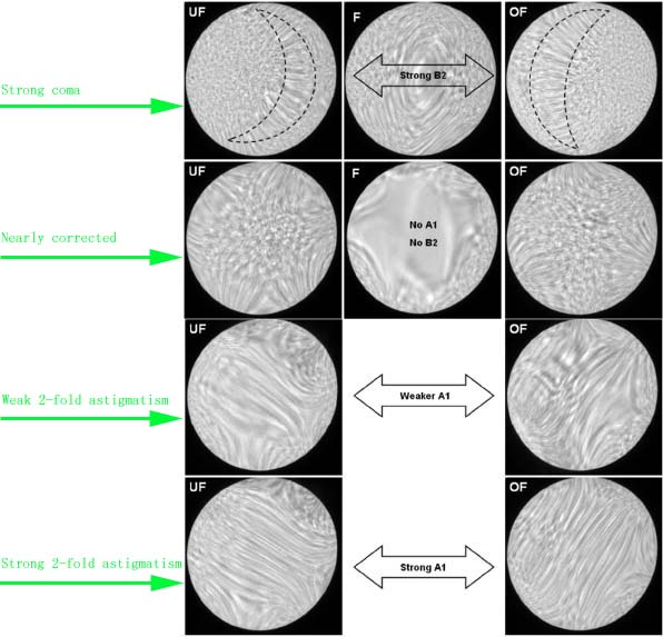
Figure 3667d. Changes of A1 and B2 from underfocus (UF) to overfocus (OF). Adapted from [2]
Figure 3667e shows the schematic comparison of Zemlin (diffractogram)-tableau characteristics for the axial aberrations up to third orders. First-order aberration (e.g. defocus and twofold astigmatism, A1) shows the elliptical distortion even without electron beam tilting because the impact of first-order aberrations does not depend on the tilt angle. For the aberrations of higher orders (n≥2), such as second-order axial coma B2, three-fold astigmatism A2, third-order spherical aberration C3 (>0), third-order star aberration S3 and four-fold astigmatism A3, there is no elliptical distortion observable for the un-tilted case. In these cases, only at illumination tilts the characteristic distortion due to the aberrations becomes discernible. Note that the higher-order aberrations have equal symmetries to the ones in Figure 3667e as discussed in page3740.
Figure 3667e. Schematic representation of Zemlin (diffractogram)-tableau characteristics for the axial aberrations up to third order.
[1] H. Akima, Y. Hirayama and T. Yoshida, Automated Alignment Cs Correction System for STEM (II): Installation of
Reinforcement Learning, www.microscopy.org, 2011 .
[2] FEI Application Instructions: How to tune STEM probe on Cs-corrected Titan.
|