=================================================================================
SOLZ (second order Laue zones) can be described by the equation given by
hu + kv + lw = 2 --------------------------------- [3901a]
where,
[uvw] -- The direction of the incident electron beam.
hkl -- The coordinates of an allowed reflection in the Nth order Laue zone.
Figure 3901a shows ZOLZ (zero-order Laue zone), FOLZ (first order Laue zones) and SOLZ.
Figure 3901a. Schematic of ZOLZ, FOLZ, and SOLZ.
However, the structure factors can cause all the reflections in a FOLZ to be forbidden so that the first ring of spots in the experimental diffraction pattern is from the second layer of the reciprocal lattice but we still call the SOLZ as the FOLZ.
According to the discussion in page4783, the radius of the SOLZ rings, G2 (nm-1 or Å-1), can be given by,
 ----------------------------- [3901b] ----------------------------- [3901b]
where,
λ -- The electron wavelength.
H -- The spacing of the reciprocal lattice planes parallel to the electron beam (nm-1 or Å-1).
The analysis of Laue zones can provide detailed information regarding the samples. For instance, √2-TTB phase of PbxNb1.17W1.0O5.93+x (x > 0.15) in Figure 3901b presented asymmetric electron diffraction patterns and exhibited systematically weak odd-order (First order here) Laue layers lying half-way between the positions of the strong even-order (zero and second order here) layers. The even-order layers correspond to the basic 3.8 Å cTTB (c axis of TTB structure) repeat. Analyses of multiple samples indicate that these weak odd-order reflections were present in the same positions as the maxima in the even layers and at the midpoint of each edge of the basic TTB square.
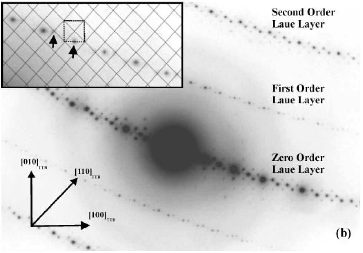
Figure 3901b. Asymmetric diffraction pattern of the √2-TTB phase of PbxNb1.17W1.0O5.93+x (x > 0.15). The inset enlargement of the first-order Laue layer shows that the black mesh defines the √2-TTB reciprocal lattice periodicity [2], and the dashed square illustrates the position of the basic TTB cell repeat with respect to the √2-TTB cell.
Adapted from [1]
[1] Sarah K. Haydon and David A. Jefferson, Quaternary Lead-Niobium-Tungsten Oxides Based on the Tetragonal Tungsten Bronze Structure, Journal of Solid State Chemistry 161, 135 - 151 (2001).
[2] S. K. Haydon, Ph.D. Thesis, University of Cambridge, 2000.
|