=================================================================================
A deflector for electron-beam deflection in EMs has been applied to align, tilt, shift, scan the electron beam, and so on. The deflector, usually including a pair of deflection coils, is called the double-deflection system.
As shown in Figure 1976a, in order to achieve a beam tilt angle of θ against the specimen, the electron beam is first tilted by θ1 in the opposite direction with the first-stage deflection coil (Def1) and then tilted back with the second-stage coil (Def2). The geometrical relation between θ1 and θ2 is given by,
 ----------------------------- [1976a] ----------------------------- [1976a]
where,
l1 -- The distance between Def1 and Def2.
l2 -- The distance between Def2 and the specimen.
By changing the current ratio for Def1 and Def2 with the balance adjuster, the beam-tilt angle θ2 can be changed.
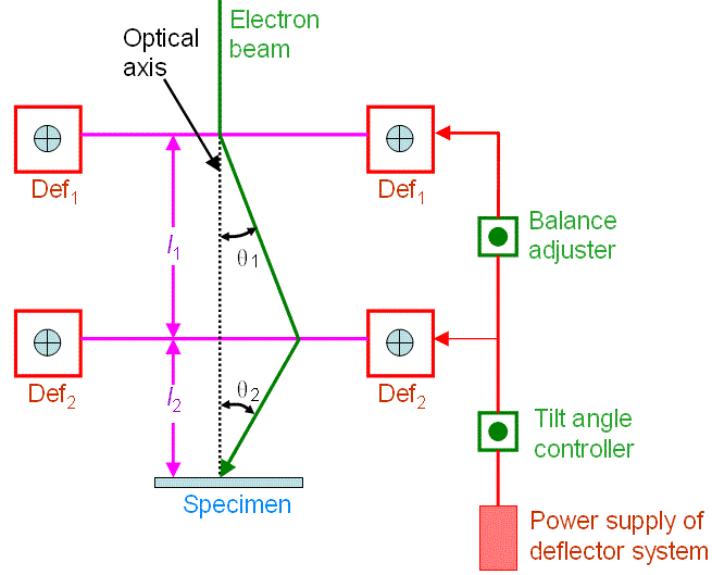
Figure 1976a. Schematic illustration of beam tilt with a deflector.
Figure 1976b shows the misalignment of an objective lens, where the off-axis electron beam enters the objective lens. For a specific lens setting, the object ABC forms an image A'B'C'. The image will be changed to A"B"C" (smaller than A'B'C') with a center (B' or B”) formed by the unchanged beam (BB' or BB”) if the objective lens setting is changed. In this case, the back focal plane of the objective lens is also changed. Furthermore, as shown in Figure 1976b (b) this change induces a rotation of the image because of the helical path of the electrons through the lens. This can happen, for instance, when the objective lens current is changed.
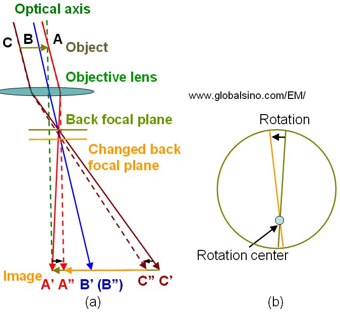
Figure 1976b. Misalignment of the objective lens: (a) Sweep of the image, and (b) Combination of sweep and rotation of the image on the viewing screen in the EM.
The beam misalignment can be corrected either by tilting the incident illumination as shown in Figure 1976c (a), or by adjusting the physical position of the objective lens pole pieces as shown in Figure 1976c (b). In Figure 1976c (b) the lower pole piece in TEM is moved so that both upper and lower pole pieces are aligned to the optical axis.
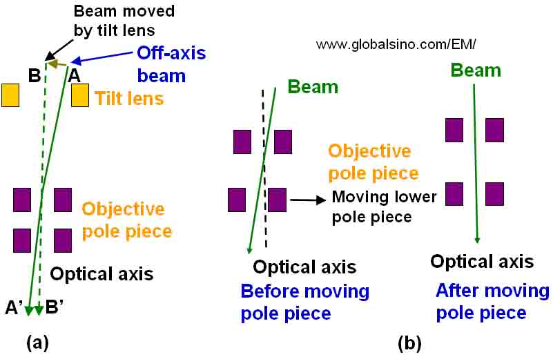
Figure 1976c. The correction of non-axial objective lens illumination by: (a) Beam tilt, and (b) Movement of the lower objective lens pole piece.
Finally, the beam alignment can be conformed by viewing the rotation center of the image on the viewing screen when the defocus of the objective lens is adjusted. If the rotation center of the image matches the center of the viewing screen, the beam alignment around the objective lens is correct.
By wobbling the condenser lens excitation and then the microscope high tension, the alignment of the illumination electron beam in STEM mode can be very accurately checked. If there is a misalignment of the beam between condenser and objective lenses, there will be a periodic translation of Ronchigram features when the wobbling takes place. This misalignment can be corrected by using the condenser alignment coils (CTEM bright tilt in JEOL systems) so that the features only oscillate in and out symmetrically about the coma-free axis.
|