=================================================================================
Besides the objective lens, intermediate (and/or diffraction) lenses and projector lenses further magnify the electron image and form the final image on the viewing screen. High-magnification CTEM imaging requires the first projector (P1) to run near its maximum strength, and the objective lens (OL) to project a focused image of the specimen into the front-focal plane of P1.
In TEM systems, the first condenser and final projector lenses have short focal length and their designs are similar to that of the objective lens. However, the second condenser and the other projector lenses may be much weaker.
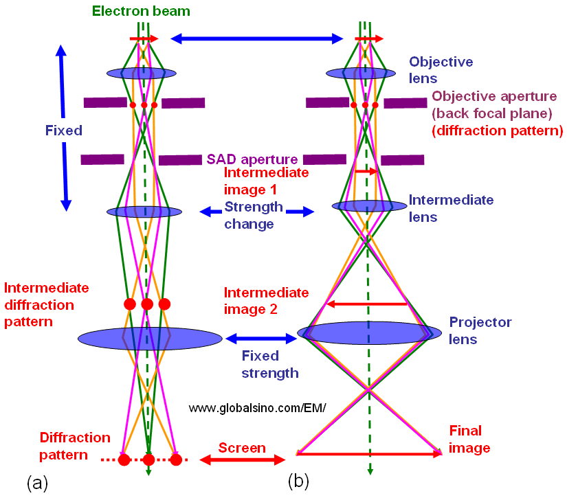
Figure 3578 shows the comparison of the lens conditions between TEM diffraction and TEM imaging modes. Those two modes are the basic modes in TEM operations. The difference between the two modes may only be the strength of the intermediate lens.

Figure 3578. Comparison of the lens conditions between TEM diffraction and TEM imaging modes.
In STEMs, the projector system normally consists of not less than two lenses that provide flexibility in choosing different camera lengths and collection angles for imaging and spectroscopy. To form Z-contrast images, the STEM objective aperture must be inserted to cut out high-angle electron rays, and an annular detector must be inserted after the projector lens system.
Unlike the negligible distortions in most CTEM analyses, distortions extremely affect off-axis electron holograms as the phase information is encoded in the bending of the interference fringes [1-3]. The origin of the distortions in off-axis electron holograms are projector lenses, local variations in TEM specimen thickness, charging of the biprism filament, and shear distortion of the fiber optic of the CCD camera. [3]
[1] Rau, W.-D., Lichte, H., Völkl, E. & Weierstall, U. (1991).
Real-time reconstruction of electron-off-axis holograms recorded
with a high pixel CCD camera. J Comput-Assist Microsc
3, 51–63.
[2] Völkl, E. & Lehmann, M. (1999). The reconstruction of off-axis
electron holograms. In Introduction to Electron Holography,
Völkl, E., Allard, L.F. & Joy, D.C. (Eds.), pp. 125–151. New York:
Kluwer Academics/Plenum Publishers.
[3] Michael Lehmann, and Hannes Lichte, Tutorial on Off-Axis Electron Holography, Microsc. Microanal. 8, 447–466, 2002.
|
