=================================================================================
The objective aperture can be inserted into the back focal plane to cut off peripheral electrons. Annular dark-field transmission electron microscopy (ADF-TEM) is widely used to evaluate the mass-thickness, atomic number and imaging of TEM samples. A simple ADF-aperture setup uses an annular objective aperture that acts as a central beam stop in the back focal plane of the objective lens [1 – 5] as shown in Figure 3891a. This aperture also blocks the outer electrons scattered at very high semiangles. Without an aperture, the contribution of TDS (Thermal diffuse scattering) to the image is significant. Therefore, the central beam and all electrons scattered at very high semiangle are excluded from imaging. By optimizing the dimension of the inner and outer rings (~ 86 µm for the inner ring and ~200 µm for the outer ring in Figure 3891a), many applications can be obtained. The SEM (secondary electron microscopy) image in Figure 3891a (b) shows an annular aperture fabricated using focused-ion-beam (FIB) technique.
Figure 3891a. a) Schematic illustration of the column of a scanning transmission electron
microscope (STEM) system. b) An ADF aperture prepared using focused-ion-beam (FIB) technique.
Note that TEM image contrast may be enhanced by using an objective aperture. As shown in Figure 3891b, in TEM bright-field (BF) mode, an objective aperture is placed in the back focal plane of the objective lens which allows only the transmitted beam to pass. In this case, mass-thickness and diffraction contrast contribute to image formation, that is thick areas, areas with heavy atoms, and crystalline areas in most crystalline orientations appear in dark contrast. The mixed contrasts make the interpretation difficult. TDS tends to occur through high-angles and thus those electrons are scattered beyond the objective apertures which are normally used in bright-field TEM imaging.
Figure 3891b. TEM bright field (BF) mode.
The local contrast on the TEM image plane is proportional to the number of electrons striking the viewing screen or detector. Objective apertures in different sizes can be selected for imaging. Figure 3891c illustrates the mechanism of diffraction contrast formation in imaging mode. a0, b0, c0, and d0 represent the rays in the incident electron beam, a1, a2, b1, c1, and d1 the rays in diffracted beams, and a3, b2, c2, and d2 the rays in the directly transmitted beam. The direction deviation of the transmitted rays from that of the incident electron beam is due to a magnification caused by the lenses between the specimen and the imaging plane. When only the a2 and d1 rays are selected with an objective aperture there are three different contrasts on the image plane:
i) (B) and (C) show dark contrast, formed in the regions of the specimen which diffract all electrons out of the image plane and/or out of the objective aperture;
ii) (A) shows gray contrast, formed in the region which diffracts some but not all electrons;
iii) (D) shows white contrast, formed in the regions through which electrons pass without diffraction.
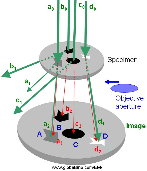
Figure 3891c. Schematic illustration of diffraction contrast formation in TEM imaging mode.
Different from bright-field (BF) TEM imaging condition, in dark-field (DF) TEM imaging condition, as shown in Figure 3891d one or more diffracted electron beams are allowed to pass the objective aperture placed in the back focal plane of the objective lens while the transmitted electron beam is blocked by the aperture. In Figure 3891d (a) a smaller aperture is used to select a single diffracted beam only, while in Figure 3891d (b) a bigger aperture is used to select two diffracted beams.
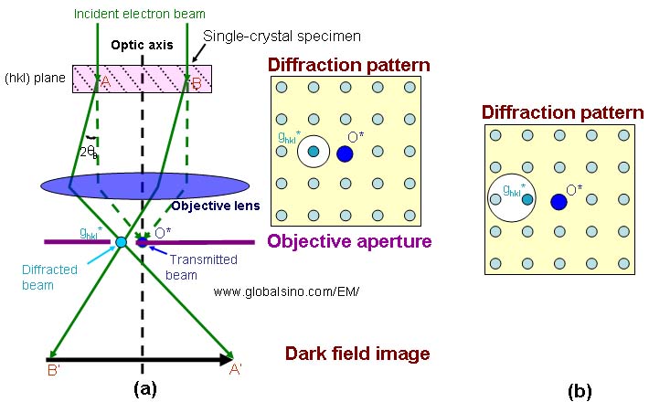
Figure 3891d. Dark-field (DF) TEM imaging conditions.
The white disks indicate objective apertures.
Figure 3891e shows the comparison of the lens conditions between TEM diffraction and TEM imaging modes. Those two modes are the basic modes in TEM operations. The difference between the two modes may only be the strength of the intermediate lens.
Figure 3891e. Comparison of the lens conditions between TEM diffraction and TEM imaging modes.
The diffraction effect of the objective aperture is important for HRTEM imaging. The radius of the Airy disk produced by the objective aperture is given by,
rAiry ~ 1.2λf/D ---------------- [3891]
where,
f -- The focal length of the lens;
D -- The aperture diameter.
Therefore, in TEM imaging, the spatial resolution degrades when a small objective aperture is used to reduce the inelastic scattering contribution to bright field images, or to exclude closely spaced spots to form dark field images.
Depending on the height change or defocus value, the caustic curve may be cut off by the objective aperture if it is inserted.
It is very important to note that the objective aperture itself can introduce astigmatism if it is not perfect centered on the optic axis.
Note that the positioning precision of an objective aperture is generally of micrometer scale.
Furthermore, in modern TEM systems, to minimize the spurious X-rays, the objective aperture needs to be removed during analysis, because the objective aperture not only generates hard X-rays and potentially damages the EDS detector, but also causes unwanted X-ray peaks in the obtained spectrum.
The schematic illustration of JEM-2010F objective lens in Figure 3891f presents the typical objective lens in conventional TEMs. The specimen (for side-entry holder) is located at the center of the polepieces. Thee objective aperture (OA) is placed immediately below the specimen and the high contrast (HC) aperture goes through the lower polepiece.
Figure 3891f. Typical objective lens in conventional TEMs.
Problems of objective apertures:
Problems can occur on the fine, coarse, or both positioning mechanisms of objective aperture strip. For instance, in some problems, only two of three positions (#1, #2, and #3) can be obtained. However, in some cases, instead of being able to have apertures #1, #2, #3, and OPEN with the full function, one has nothing, #1, #2, and OPEN or other combinations. For trouble shooting, EDS detection can help diagnose what is the problem.
Furthermore, the aperture strip can also be damaged or even drop down into the microscope column if the strip was twisted incorrectly during manual operation.
High-resolution lattice fringes:
In TEM, when the transmitted beam and a diffracted beam (e.g. from (hkl) plane) pass through a large objective aperture, interference takes place between the transmitted and diffracted beam, resulting in one-dimensional (1D) lattice fringes of the (hkl) plane. When more diffracted beams together with the transmitted beam pass through, then two-dimensional (2D) high-resolution lattice fringes are obtained.
[1] K. Heinemann, H. Poppa, Phys. Rev. Lett. 1972, 20, 122.
[2] Z. L. Wang, A. T. Fisher, Ultramicroscopy 1993, 43, 183.
[3] Z. L. Wang, Ultramicroscopy 1994, 53, 73.
[4] S. Bals, B. Kabius, M. Haider, V. Radmilovic, C. Kisielowski, Solid
State Commun. 2004, 130, 675.
[5] S. Bals, R. Kilaas, C. Kisielowski, Ultramicroscopy 2005, 104, 281.
|