|
|
Standard Indexed Diffraction Patterns for fcc Crystals
- Practical Electron Microscopy and Database -
- An Online Book -
|
|
https://www.globalsino.com/EM/
|
|
This book (Practical Electron Microscopy and Database) is a reference for TEM and SEM students, operators, engineers, technicians, managers, and researchers.
|
=================================================================================
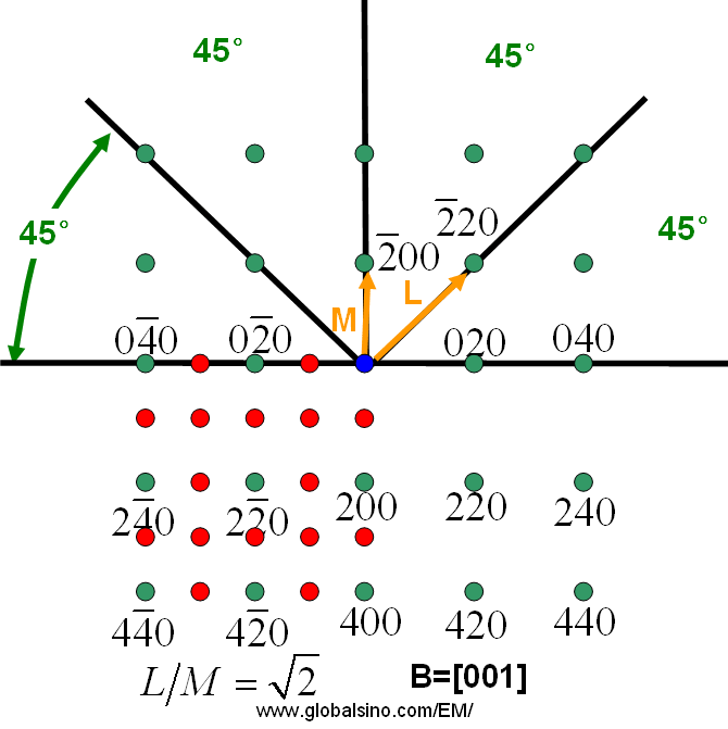
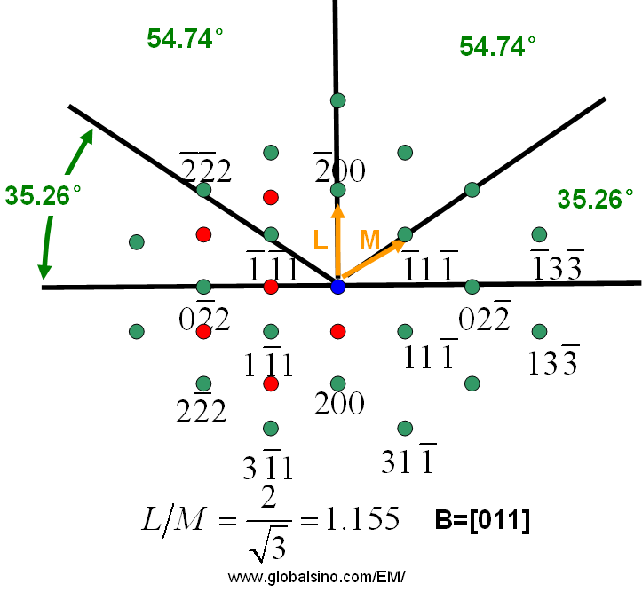
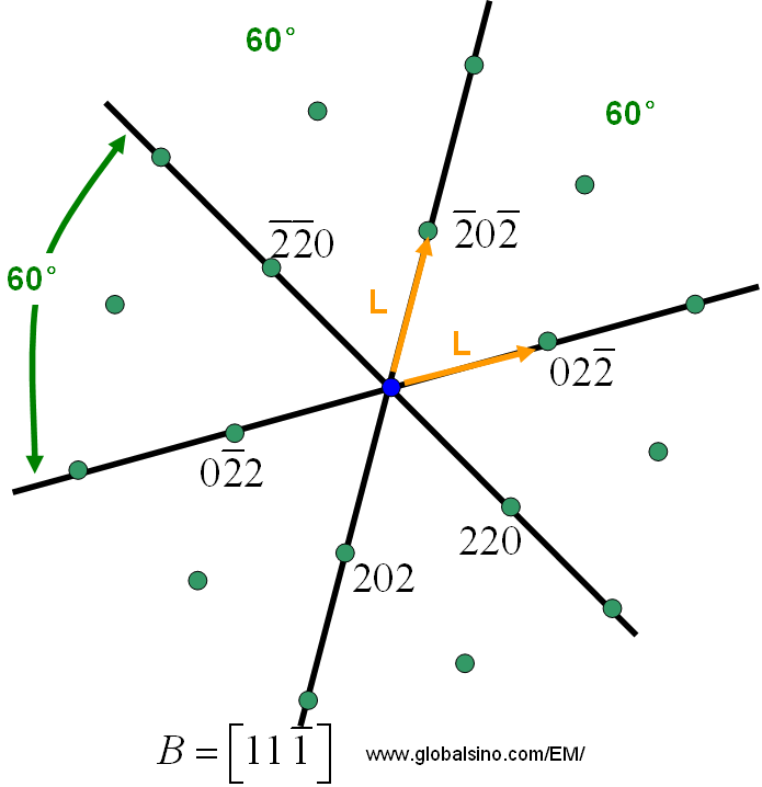
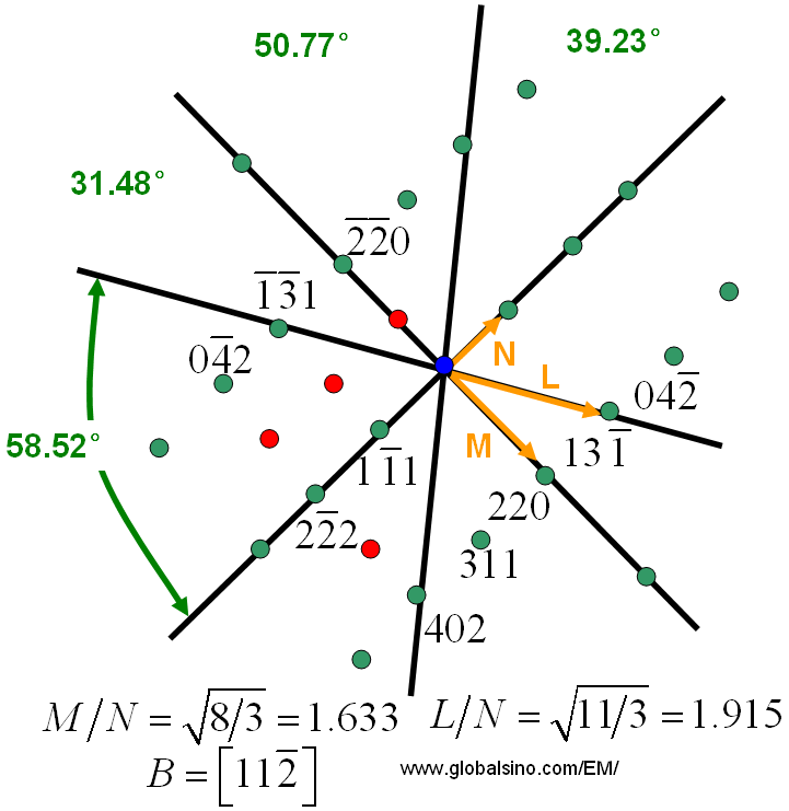
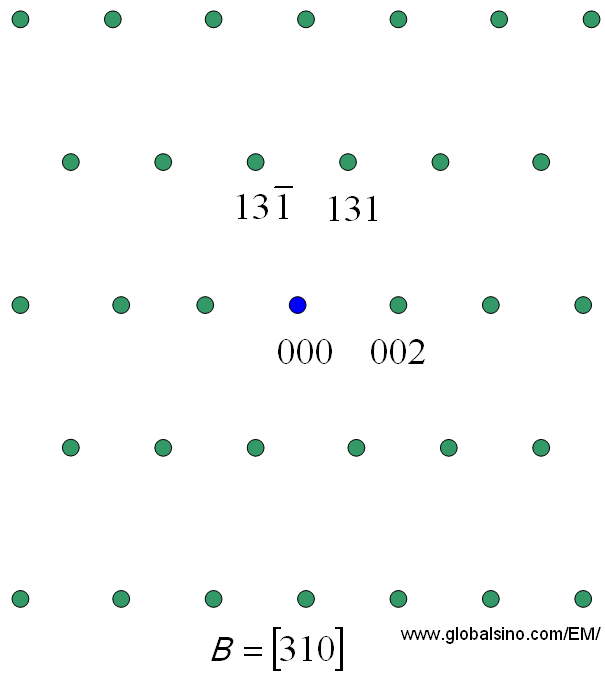
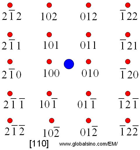
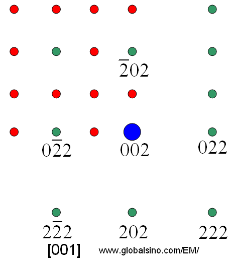
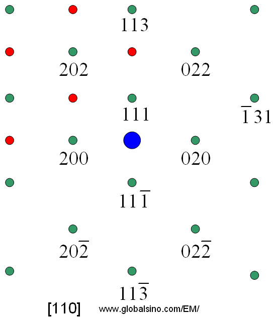
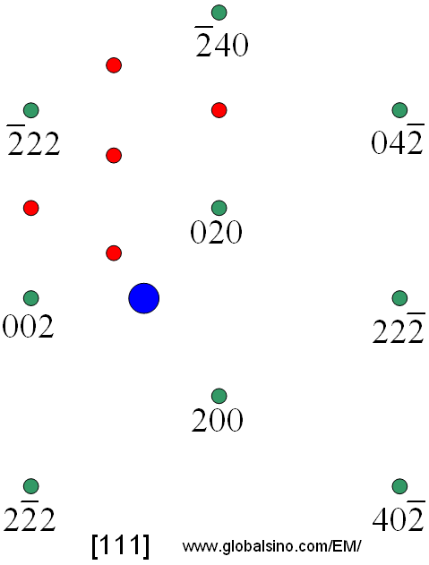
Figure 3915a shows the standard indexed diffraction patterns for fcc crystals. The ratios of the principal spot spacings are shown as well as the angles between the principle plane normals. Forbidden refelections are indicated in red.
Figure 3915a. Standard indexed diffraction patterns for fcc crystals.
The diffraction patterns listed in Figure 3915a are normally good enough in diffraction analyses because we either only need simple study of material structures for routine work or rarely find higher order reflections (the Ewald sphere intercepts the HOLZ at large scattering angles). Otherwise, we call the indexed patterns in Figure 3915a as ZOLZ patterns for better description, here, hU + kV + lW = 0. On the other hand, the higher order diffraction patterns are called FOLZ pattern, SOLZ pattern, and so on.
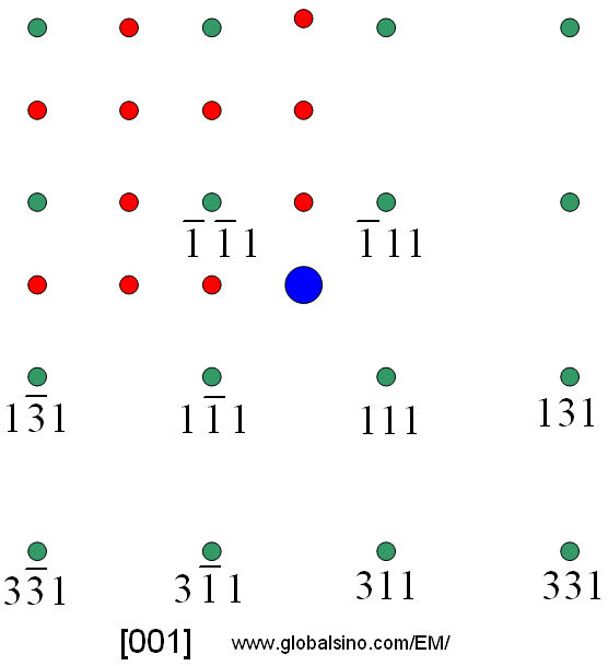
Figure 3915b shows the possible FOLZ (first order Laue zone) reflections for three principal zone axes of an fcc specimen.
Here, hU + kV + lW = 1.
Figure 3915b. The possible FOLZ (first order Laue zone) reflections for three principal zone axes of an fcc specimen. Allowed reflections are shown as green dots, forbidden reflections are indicated in red, and the blue dot shows the directly transmitted electron beam.
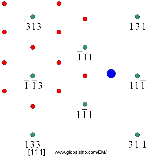
Figure 3915c shows the possible SOLZ (second order Laue zone) reflections for three principal zone axes of an fcc specimen. Here, hU + kV + lW = 2.
Figure 3915c. The possible SOLZ reflections for three principal zone axes of an fcc specimen. Allowed reflections are shown as green dots, forbidden reflections are indicated in red, and the blue dot shows the directly transmitted electron beam.
|
=================================================================================
The book author (Yougui Liao) welcomes your comments, suggestions, and corrections, please click here for submission. If you let book author know once you have cited this book, the brief information of your publication will appear on the “Times Cited” page.
|
|
