=================================================================================
FOLZ (first order Laue zone) reflections are very sensitive to atom positions. The FOLZ is formed as a ring surrounding the ZOLZ reflections near the center and can be described by the equation given by
hu + kv + lw = 1 --------------------------------- [3902a]
[uvw] -- The direction of the incident electron beam.
hkl -- The coordinates of an allowed reflection in the Nth order Laue zone.
Figure 3902a shows ZOLZ (zero-order Laue zone), FOLZ and SOLZ (second order Laue zones).
Figure 3902a. Schematic of ZOLZ, FOLZ, and SOLZ.
However, the structure factors can cause all the reflections in a FOLZ to be forbidden so that the first ring of spots in the experimental diffraction pattern is from the second layer of the reciprocal lattice but we still call the SOLZ as the FOLZ.
Note that to experimentally observe FOLZ reflections, the TEM specimen should normally be carefully tilted along mirrors until FOLZ areas appear on the pattern and long exposure time is normally needed since such reflections are often far away from the center of the screen and are weak.
The analysis of Laue zones can provide detailed information regarding the samples. For instance, √2-TTB phase of PbxNb1.17W1.0O5.93+x (x > 0.15) in Figure 3902b presented asymmetric electron diffraction patterns and exhibited systematically weak odd-order (First order here) Laue layers lying half-way between the positions of the strong even-order (zero and second order here) layers. The even-order layers correspond to the basic 3.8 Å cTTB (c axis of TTB structure) repeat. Analyses of multiple samples indicate that these weak odd-order reflections were present in the same positions as the maxima in the even layers and at the midpoint of each edge of the basic TTB square.
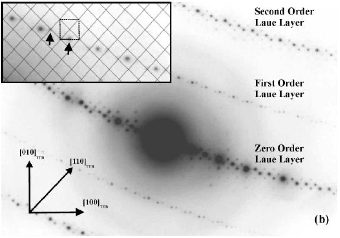
Figure 3902b. Asymmetric diffraction pattern of the √2-TTB phase of PbxNb1.17W1.0O5.93+x (x > 0.15). The inset enlargement of the first-order Laue layer shows that the black mesh defines the √2-TTB reciprocal lattice periodicity [2], and the dashed square illustrates the position of the basic TTB cell repeat with respect to the √2-TTB cell.
Adapted from [1]
The electron diffraction pattern in Figure 3902c shows both ZOLZ and FOLZ reflections obtained from Zr41Ti14Cu12.5Ni10Be22.5 in [100] zone axis. Due to the absence of ZOLZ/FOLZ periodicity difference, we can know that there is no glide plane perpendicular to the [100] direction.
![Electron diffraction pattern obtained from Zr41Ti14Cu12.5Ni10Be22.5 in [100] zone axis](image2/3902c.gif)
Figure 3902c. Electron diffraction pattern obtained from Zr41Ti14Cu12.5Ni10Be22.5 in [100] zone axis. The lattice parameters are a = 0.34 nm, and c = 1.137 nm.
[3]
CBED technique can be used to determine lattice parameters of crystals.
By measuring the radius of the FOLZ (the first HOLZ) ring of CBED patterns (e.g. the [0001] CBED pattern in Figure 3902d) under consideration
of Ewald construction, the distance between the reciprocal lattice planes parallel to electron radiation can be calculated by,
 -------------------------------------- [3902b] -------------------------------------- [3902b]
where,
G -- The radius of the FOLZ ring.
H -- The distance between the plane of reciprocal
lattice.
λ -- The electron wavelength.
For high voltage TEM (e.g. 200 keV, λ= 0.0025 nm, see page4787), since 2/λ >> H, Equation 3902b can be simplified by,
 -------------------------------------- [3902c] -------------------------------------- [3902c]
For some crystals (e.g. cubic systems), the length (c) of c-axis is equal to 1/H. Therefore, in real space, Equation 3902c becomes,
 -------------------------------------- [3902d] -------------------------------------- [3902d]
In this case, c denotes the lattice parameter c.
Note that in reality the FOLZ ring depends on both dynamic
and kinematic scattering in the TEM specimen.
[1] Sarah K. Haydon and David A. Jefferson, Quaternary Lead-Niobium-Tungsten Oxides Based on the Tetragonal Tungsten Bronze Structure, Journal of Solid State Chemistry 161, 135 - 151 (2001).
[2] S. K. Haydon, Ph.D. Thesis, University of Cambridge, 2000.
[3] Q. Wei, N. Wanderka, P. Schubert-Bischoff, and M-P. Macht, S. Friedrich, Crystallization phases of the Zr41Ti14Cu12.5Ni10Be22.5 alloy after slow solidification, J. Mater. Res., 15 (8) 1729, (2000).
[4] Kenneth S. Vecchio and David B. WILLIAMS, Convergent Beam Electron Diffraction Analysis of the T1 (Al2CuLi) Phase in Al-Li-Cu Alloys, Metallurgical Transactions A, 19A, 1988-2885, (1988).
|
![[0001] CBED patterns of T1 (Al2CuLi) crystals: whole-pattern symmetry (HOLZ)](image2/2991a.jpg)