=================================================================================
Ion pumps employ ionization process to remove air in EMs by emitting electrons from a cathode and then by ionizing air molecules due to plasma discharge with a high voltage between anode and cathode as shown in Figure 4320a. The ionization probability is improved by the presence of the magnetic field because the electrons may travel on spiral trajectories. The energetic gas (e.g. argon in air) ions then sputter Ti (titanium) atoms on the cathode and are deposited on the other parts of the pump chamber even though the gas atoms are mainly trapped on the cylindrical anode. In this process, the Ti atoms react with the rest gas and thus increase the pumping efficiency. Note that the ion pump does not remove the rest gases from the EM system, but just make the gases do not contribute to the pressure any more. On the other hand, in general, ion pumps are only turned on after a diffusion pump has lowered the pressure to <~10-3 Pa (10-5 Torr) because of the reasons below:
i) Ion pumps are only efficient at high vacuums.
ii) It becomes a problem if a large amount of water is pumped by an ion pump. In fact, titanium reacts very easily with water to form an oxide and liberate hydrogen, which cannot be efficiently adsorbed.
iii) The active pump material, e.g. Ti, will be all sputtered from the cathode, and thus the ion pump has a finite lifetime and must finally be replaced. This lifetime is normally many years. Note that using the ion pumps at high pressures will also decrease their lifetime.
Because of the same reason, ion pumps are often directly added to the specimen stage (especially for analytical EMs) or gun chambers of EMs to enhance the vacuum in these important regions. In case of any vacuum accident, the pump will be turned off automatically by a programmed setup if the ion current increases too much at low vacuum pressures.
Figure 4320a. Principle of ion pump.
As an example, Figure 4320b shows the location of ion getter pumps in a TEM system. The high and ultra-high vacuum in the gun and specimen areas can be reached at a vacuum of < 10-6 Pa with this type of ion pumps.
Figure 4320b. Schematic illustration of pumping system in TEMs.
Note that most ion pumps are not good at pumping hydrogen. On the other hand, ion pumps do not contain oil, so that they do not contaminate the EM column. Furthermore, the current between the electrodes in ion pumps is proportional to the pressure in the system. Therefore, the pump itself can be used to estimate the vacuum level, like a vacuum gauge, by converting an analog format to a digital signal and then a number readout. As the vacuum improves there are less air molecules to be ionized. The final vacuum for a typical ion pump is less than 10-8 torr. The high vacuum produced by diffusion pumps, turbomolecular pumps and ion getter pumps is normally measured by Penning gauges.
Both ion getter pumps and cryo-pumps are often employed in applications requiring extremely clean, ultrahigh vacuums, e.g. in LaB6 guns and FEGs. As shown in Figure 4320c (a), in most modern TEMs, the electron gun, top lenses, and specimen chamber are maintained at ultra-high vacuum by an ion pump, while the viewing screens and photographic chamber are maintained at a lower vacuum, which is referred to as high vacuum, by either a diffusion pump or a turbomolecular pump. This vacuum level is backed by a mechanical (rotary) pump. However, some TEMs have lower vacuum in the specimen chamber as shown in Figure 4320c (b). In fact, the main difference between the two types of microscopes is whether or not the specimen contamination is reduced by ion pumps.
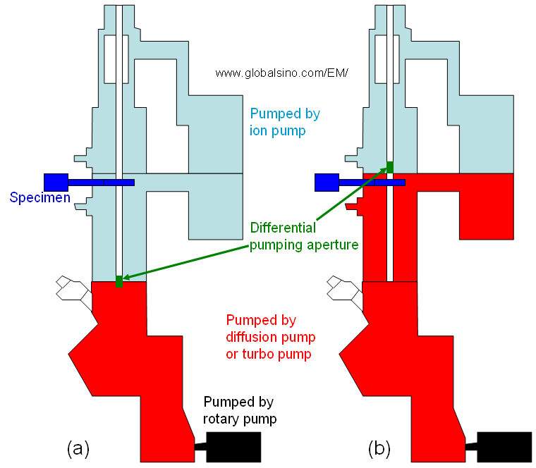
Figure 4320c. Vacuum in TEMs: (a) Modern TEMs, and (b) Some TEMs.
Mostly, microelectronics industry has the need of the cleanest microscope columns. For instance, after the semiconductor wafers, containing numerous microelectronic devices, are observed with SEMs, various fabrication processes will continue. Therefore, the wafers cannot be contaminated during SEM observation. The vacuum configuration of the microscopes for this application would probably have a scroll pump used to rough out and to back a turbomolecular pump for the specimen chamber. In addition, ion getter pumps are typically attached to the electron electron gun and the upper portion of the column. In this case, the three types of pumps can provide the cleanest SEM system.
|