=================================================================================
The electron gun in electron microscopes generates electrons and provides the first coherent crossover of electron beam (see schematic diagram). In the electron guns of conventional electron microscopes, resistance heating is produced in the gun filaments and electrons are boiled off the tip by thermionic emission.
Figure 1975a shows the structure of the electron probe-forming system in STEM mode in JEOL JEM-2010F TEMs. A setup, consisting of electrostatic gun lens and twin condenser lens system, controls the de-magnification of the Schottky field emission source. Compared to the cold field emitter, the Schottky electron source has a much larger emission area. Each element of the electron source can be assumed to emit electrons incoherently and thus results in an incoherent broadening of the probe [1]. A large de-magnification factor between the source and probe reduces this probe-broadening effect. In addition, the beam current decreases due to the probe-forming aperture. A cross-over is formed between the two condenser lenses (C1 and C2) by employing near-maximum excitation in the C1 lens, resulting in a large source de-magnification. The C2 lens and the gun lens are used to tune the probe coherence further by setting the probe size. In the STEM mode, both condenser and objective mini-lenses are tuned off.
Figure 1975a. Schematic illustration of the probe-forming electron optics in STEM mode in JEOL JEM-2010F TEMs.
The schematic illustration in Figure 1975b presents the position of electron gun part in typical TEM systems.
 |
1. Electron gun
2. Wehnelt unit
3. Anode
4. Electron gun second beam delector coil
5. Anode chamber isolation valve
6. 1st condenser lens coil
7. Condenser polepiece
8. 3rd condenser lens coil
9. Condenser aperture assembly
10. Specimen chamber
11. Goniometer
12. specimen holder
13. Stigmator screening cylinder
14. Objective lens coil
15. Objective lens liner tube
16. Field limiting aperture
17. Intermediate lens stigmator
18. Intermediate polepiece
19. Intermediate lens linear tube
20. Projector lens beam deflector coil
21. Projector upper polepiece
22. Projector lower polepiece
23. Binoculars
24. Viewing chamber
25. Viewing window
26. Dispensing magazine
27. Receiving magazine
28. Camera chamber
29. Lift arm
30. HT cable to high voltage tank
31. Anode chamber, or called acceleration tube
32. Gas inlet
33. Electron gun 1st beam deflector coil
34. Condenser lens stigmator coil
35. Spot alignment coil
36. Condenser lens 1st beam deflector coil
37. Condenser lens 2nd beam deflector coil
38. Condenser minilens (CM) lens coil
39. Stage heater
40. Objective polepiece
41. Objective lens stigmator coil
42. 1st image shift coil
43. Objective minilens (OM) lens coil
44. 2nd image shift coil
45. 1st intermediate lens coil
46. 2nd intermediate lens coil
47. 3rd intermediate lens coil
48. Projector lens coil
49. Viewing chamber isolation valve
50. High resolution diffraction chamber
51. Small screen
52. Large screen |
Figure 1975b. Schematic illustration of the structure of typical TEM systems (e.g. JEM-2010F
here). |
For TEM analysis, the size of electron source must be large to achieve a large area of illumination with sufficient electron density. From this point of view, thermionic sources are more than capable of meeting these criteria. However, this relatively large source size in addition to a large electron energy spread means that thermionic sources are not applicable to scanning probe microscopy and EELS microanalysis.
A field emission gun (FEG) is needed for electron holography since the spatial coherence with a conventional electron gun extremely limits the resolution. Note that even though for a TEM with a conventional electron gun, a smaller illumination aperture can be used to increase the degree of coherence, the smaller aperture still cannot practically be used for holography measurement because of the smaller coherent beam current Icoh.
Ion pumps are often directly added to the specimen stage (especially for analytical EMs) or gun chambers of EMs to enhance the vacuum in these important regions. As shown in Figure 1975c (a), in most modern TEMs, the electron gun, top lenses, and specimen chamber are maintained at ultra-high vacuum by an ion pump, while the viewing screens and photographic chamber are maintained at a lower vacuum, which is referred to as high vacuum, by either a diffusion pump or a turbomolecular pump. This vacuum level is backed by a mechanical (rotary) pump. However, some TEMs have lower vacuum in the specimen chamber as shown in Figure 1975c (b).
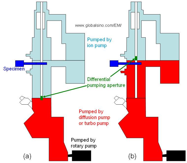
Figure 1975c. Vacuum in TEMs: (a) Modern TEMs, and (b) Some TEMs.
[1] J.M. Cowley, Image contrast in transmission scanning
electron microscopy, Appl. Phys. Lett. 15 (1969) 58-60.
|