| One microscope approximately consists of 30 thousands parts. Following the path of the electron beam in the conventional TEM (CTEM) column, the microscope can be divided as follows:
i) Electron source (or called electron gun).
ii) High voltage generator and acceleration tube.
iii) Illumination lens system and deflector.
iv) EDS system (optional).
v) Specimen holder and stage.
vi) Image-forming lens system.
vii) Viewing chamber and camera chamber.
viii) EELS and/or EFTEM system (optional).
Table 4554 lists the major column components and their functions of a TEM system.
Table 4554. Major column components and their functions of a TEM system.
Component |
Synonyms |
Function of components |
Illumination |
| Electron gun |
Gun, source |
Generates electrons and provides the first coherent crossover of electron beam |
| Condenser lens 1 |
C1, Spot size |
Determines the smallest illumination spot size on specimen |
| Condenser lens 2 |
C2, Brightness |
Varies amount of illumination on specimen—in combination with C1 |
| Condenser aperture |
C2 aperture |
Reduces spherical aberration, helps control amount of illumination striking
specimen |
Specimen manipulation |
| Specimen exchanger |
Specimen air lock |
Chamber and mechanism for inserting specimen holder |
| Specimen stage |
Stage |
Mechanism for moving specimen inside the column of the microscope |
Imaging system |
| Objective lens |
OL |
Forms, magnifies, and focuses first image |
| Objective aperture |
OL aperture |
Controls contrast and spherical aberration |
| Intermediate lens |
Diffraction lens |
Normally used to help magnify image from objective lens and to focus
diffraction pattern |
| Intermediate aperture |
Diffraction aperture, field
limiting aperture, selected area diffraction aperture |
Selects area to be diffracted |
| Projector lens 1 |
P1 |
Helps magnify image, possibly used in some diffraction work |
| Projector lens 2 |
P2 |
Observation and imaging systems |
| Viewing chamber |
|
Contains viewing screen for final image |
| Binocular microscope |
Focusing scope |
Magnifies image on viewing screen for accurate focusing |
| Camera |
|
Contains film for recording images |
| Charge-coupled device |
CCD |
Records images in digital format |
A schematic of an electron-optical column of a TEM is
shown in Figure 4554a.
Figure 4554a. Schematic of an electron-optical column of a TEM system.
Figure 4554b shows the schematic illustration of a TEM system with a slightly different optics in a different way.
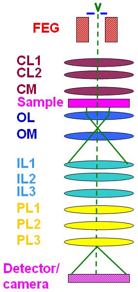
Figure 4554b. Schematic illustration of a TEM system with a slightly different optics in a different way.
Most parts in EMs have not been improved in many years except most of the conventional electron guns have been replaced by the field emission guns and the aberration correctors are introduced recently. For instance, in TEM systems, the sample stages, electron guns, round lenses, objective lens (OL) polepieces, and detectors available in current systems are very similar to the best available in 1980s. Figure 4554c shows the schematic illustration of the structure of typical TEM systems.
 |
1. Electron gun
2. Wehnelt unit
3. Anode
4. Electron gun second beam delector coil
5. Anode chamber isolation valve
6. 1st condenser lens coil
7. Condenser polepiece
8. 3rd condenser lens coil
9. Condenser aperture assembly
10. Specimen chamber
11. Goniometer
12. specimen holder
13. Stigmator screening cylinder
14. Objective lens coil
15. Objective lens liner tube
16. Field limiting aperture
17. Intermediate lens stigmator
18. Intermediate polepiece
19. Intermediate lens linear tube
20. Projector lens beam deflector coil
21. Projector upper polepiece
22. Projector lower polepiece
23. Binoculars
24. Viewing chamber
25. Viewing window
26. Dispensing magazine
27. Receiving magazine
28. Camera chamber
29. Lift arm
30. HT cable to high voltage tank
31. Anode chamber, or called acceleration tube
32. Gas inlet
33. Electron gun 1st beam deflector coil
34. Condenser lens stigmator coil
35. Spot alignment coil
36. Condenser lens 1st beam deflector coil
37. Condenser lens 2nd beam deflector coil
38. Condenser minilens (CM) lens coil
39. Stage heater
40. Objective polepiece
41. Objective lens stigmator coil
42. 1st image shift coil
43. Objective minilens (OM) lens coil
44. 2nd image shift coil
45. 1st intermediate lens coil
46. 2nd intermediate lens coil
47. 3rd intermediate lens coil
48. Projector lens coil
49. Viewing chamber isolation valve
50. High resolution diffraction chamber
51. Small screen
52. Large screen |
Figure 4554c. Schematic illustration of the structure of typical TEM systems (e.g. JEM-2010F
here). |
An image or diffraction pattern from the specimen can be obtained on a fluorescent screen. Image contrast may be enhanced by using an objective aperture, and the area for diffraction may be selected by a selected area aperture. The image is focused with the objective lens and magnification is controlled by the intermediate and/or diffraction lens. |
