Chapter/Index: Introduction | A | B | C | D | E | F | G | H | I | J | K | L | M | N | O | P | Q | R | S | T | U | V | W | X | Y | Z | Appendix
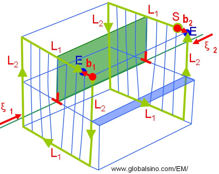
| Figure 3459 shows the schematic illustration of sense vector, and Burgers vector and circuits for an edge dislocation. Refer to relevant pages for notations (i.e. sense vector, Burgers vector, and Burgers circuits ).
Figure 3459. Schematic illustration of sense vector, and Burgers vector and circuits for an edge dislocation. Regardless of whether the dislocations are of edge- or screw-type, based on the invisibility criterion, the dislocations are invisible at g·b = 0 or exhibit a so-called "residual" contrast for edge dislocations when the dislocations are out of contrast [1], the dislocations are visible in the other cases. For a pure edge dislocation the sense vector and Burgers vectors are perpendicular to each other so that their dot product is zero, On the other hand, when the sense vector is reversed, the resulting Burgers vector is also reversed. Therefore, one of the characteristics of the dislocations is represented by the cross product of the sense vector and the Burgers vector, always pointing to the extra half plane of atoms that defines the edge dislocation: Furthermore, a glide dislocation is generally a line boundary between the slipped and unslipped portions of the glide (slip) plane. The line is not necessary to be straight. When it is curved some parts can be a screw dislocation and some parts an edge dislocation. For a given sense vector that points in one direction along the dislocation, the Burgers vector is invariant.
[1] Hirsch, P., Howie, A, Nicholson, R.B., Pashley, D.W. and Whelan, M.J., 1977, Electron Microscopy of Thin Crystals, Krieger, New York, p. 181.
|