=================================================================================
There are two methods normally used for spherical aberration correction at high accelerating voltages in TEM and STEM: i) Using magnetic hexapoles with transfer round lenses [1] in both TEM and STEM system; ii) Combining four magnetic quadrupoles and at least three octupoles in STEM system [2] due to its off-axis aberrations. Probe-forming Cs-correctors are also called STEM Cs-correctors.
In STEM, there is only a condenser system, which is a lens used to form a fine probe. Sometimes this lens is also called objective lens. The correction of the spherical aberration of the pre-field lens is much cheaper comparing to post-field corrections. The main advantage of such correction is to reduce the beam tails so that a fine beam can be positioned at a specified column of atoms and does not spread its intensity into neighboring columns significantly. This tail spilling is critical for high resolution Z-contrast (HAADF) imaging and EELS analysis.
Figure 4263a shows an example of microscopes with the Cs (spherical aberration)-correctors for both probe-and image-forming systems. The image-forming Cs-corrector is mounted between the objective lens and the intermediate lens, and the probe-forming Cs-corrector is between the condenser lens and the condenser mini-lens. The height of each corrector is 25 cm.
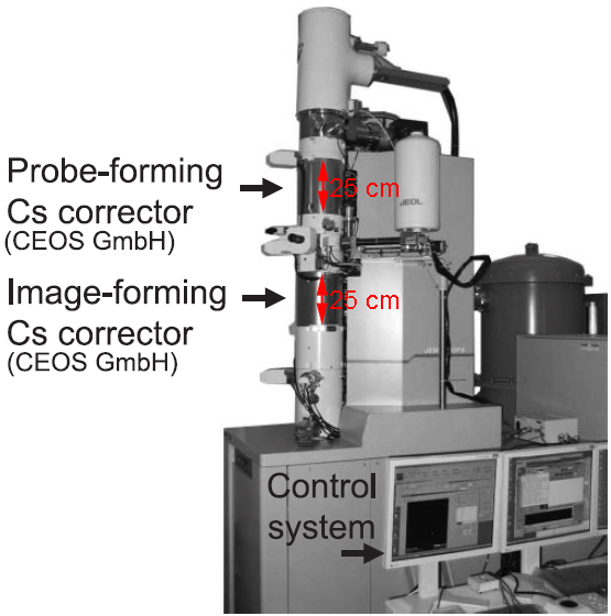
Figure 4263a. JEM-2200FS TEM/STEM with probe-and image-forming Cs-correctors. Adapted from [3].
Figure 4263b shows the photograph of a LVEM (low-voltage electron microscope) with delta Cs correctors operated in the range 30 - 60 kV. The CFEG stands for cold field emission gun installed on the top of the column. The delta correctors for STEM and TEM are integrated for both probe- and image-forming systems. An Enfina spectrometer is installed at the bottom of the column for EELS-based measurements.
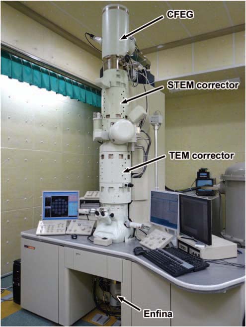
Figure 4263b. The photograph of a LVEM with delta Cs correctors operated in the range 30 - 60 kV. [4]
In order to optimize the acquisition of holograms, in many cases, the microscopes need to be re-configured. For instance, Cooper et al. [5] turned off the probe corrector in their FEG FEI Titan microscope even though it had been installed. Both the objective lens and third condenser lens were turned off, and a Lorentz lens was used in order to extend the holographic field of view to 1500 x 700 nm2.
[1] Haider, M., Braunshausen, G. and Schwan, E. 1995. Correction of the spherical aberration of a 200 kV TEM
by means of a hexapole-corrector, Optik, 99, 167–179.
[2] Krivanek, O. L., Dellby, N., and Lupin, A. R. 1999. Towards sub-Å electron beams, Ultramicroscopy, 78,
1–11.
[3] Hidetaka Sawada, Takeshi Tomita, Mikio Naruse, Toshikazu Honda, Paul Hambridge, Peter Hartel, Maximilian Haider, Crispin Hetherington, Ron Doole, Angus Kirkland, John Hutchison, John Titchmarsh and David Cockayne, Experimental evaluation of a spherical aberration-corrected TEM and STEM, J Electron Microsc (Tokyo) (2005) 54 (2): 119-121. doi: 10.1093/jmicro/dfi001.
[4] Takeo Sasaki, Hidetaka Sawada, Fumio Hosokawa, Yuji Kohno, Takeshi Tomita, Toshikatsu Kaneyama, Yukihito Kondo, Koji Kimoto, Yuta Sato, and Kazu Suenaga, Performance of low-voltage STEM/TEM with delta corrector and cold field emission gun, Journal of Electron Microscopy 59(Supplement): S7–S13 (2010).
[5] David Cooper, Pierrette Rivallin, Jean-Michel Hartmann, Amal Chabli, and Rafal E. Dunin-Borkowski, Extending the detection limit of dopants for focused ion beam prepared semiconductor specimens examined by off-axis electron holography, JOURNAL OF APPLIED PHYSICS 106, 064506 (2009).
|