Chapter/Index: Introduction | A | B | C | D | E | F | G | H | I | J | K | L | M | N | O | P | Q | R | S | T | U | V | W | X | Y | Z | Appendix
| Both the words “sextupole” and “hexapole” are essentially talking about the same thing in EMs. It is called sextupole since the arrangement of its pole pieces has sixfold symmetry, while the name “hexapole” introduces one Greek-based number in a set of Latin-based numbers and is easier to pronounce. In aberration-corrected EMs (electron microscopes) a combination of hexapole or octupole lenses are used in a aberration corrector which lacks rotational (circular) symmetry and thus doesn’t have to have a positive spherical aberration like conventional, round magnetic lenses. Note that quadrupole–octupole correctors are essential to compensate for both the chromatic and spherical aberrations, while a hexapole correctors are used to remove the spherical aberration. Nowadays, high resolutions (e.g. ~ 1.2 Å) are routinely reached with the hexapole correctors and the best contrast for crystalline materials has been obtained by tuning the third-order coefficient (C3,0) of the spherical aberration to negative values [1]. As an extension, asymmetric dodecapole-type spherical aberration correctors, developed by Hosokawa et al. [5], are widely utilized in STEM and TEM. In general, the residual secondary aberration of the hexapoles is a third-order spherical aberration (Cs) with opposite sign to that of the round lenses. The magnitude of this secondary aberration is proportional to the square of the hexapole strength. Therefore, it is always possible to compensate for the Cs of the round lenses by exciting the hexapoles properly. Figure 4314a shows the hexapole design for Cs correction. The optical axis, along which the electrons travel, is into the page.
Figure 4314a. The hexapole design for spherical aberration (Cs) correction.
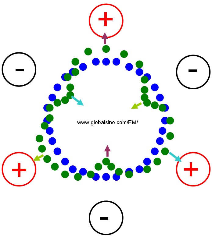
Assuming a ray has a threefold symmetry at a distance r from the optic axis when it enters the magnetic field of the hexapole, it will experience a small deflection proportional to |r|2. Due to the threefold symmetry of the magnetic field, a pair of rays on opposite sides of the optic axis (r and -r) will be deflected proportional to |r|2 in the same direction as shown by the pairs of arrows in the same colors in Figure 4314. In addition, small deflections also exist proportional to |r|3 in opposite directions.
Figure 4314b. Displacement of rays through a hexapole field in the view direction along the optical axis. The small solid circles in blue represent the rays before deflected by the magnetic field, while the ones in green represent them after deflected. The poles are marked by plus and minus signs. Note that the secondary effects of sextupoles produce spherically symmetric 3rd-order aberrations as the round lenses if paraxial optics is rotationally symmetric. These secondary aberrations depend quadratically on the sextupole strength. This behavior results from the nonlinear forces of the sextupole fields. Therefore, magnetic hexapoles combined with transfer round lenses [2] are used for third-order spherical aberration correction at high accelerating voltages in TEM and STEM. However, the image quality can be improved by this correction only if the primary 2nd-order aberrations of the sextupoles are eliminated as well and if the 4th-order aberrations can be kept adequately small. Furthermore, sextupole elements can be conveniently used to produce three-fold symmetry of electromagnetic fields. In other words, the sextupole corrector can only be applied in a TEM if all the deviations of the three-fold path cancel out in the region behind the corrector. The course of the deviation of the second order path along the optic axis depends on the arrangements and locations of both the round lenses and the sextupoles. These elements are normally employed in charged-particle optics to compensate for the primary second-order aberrations arising in the systems with a curved optical axis, such as spectrometers or imaging energy filters. Sextupoles cannot be used to correct spherical aberrations if both the signs of the aberrations generated by sextupoles and round lenses are the same. Unfortunately, this is exactly the case if the second-order aberrations are eliminated. However, it is possible to reverse the sign of the spherical aberration by employing a round lens doublet. Figure 4314c shows the simplest system which can eliminate all second-order fundamental rays and thus all the second-order aberrations outside of the corrector. It consists of a round lens doublet and two identical sextupoles. The outer focal points of the corrector are the same as the nodal points N1 and N2 of the round lens doublet. The coils of the round lenses are connected oppositely in order to avoid an image rotation from the first sextupole, which is independent of the current strength. Therefore, the doublet images the front sextupole with magnification of −1 exactly onto the second sextupole centered about the nodal point N2 without introducing an off-axial third-order coma. This system can correct the third-order spherical aberrations of electron microscopes [3]. Note that the system shown in Figure 4314c neither introduces coma nor distortion due to the symmetry of the hexapole field.
Figure 4314c. Schematic illustration of a simplest spherical-aberration corrector. Adapted from [4]. Figure 4314d shows the full view of of the practical double-sextupole Cs correctors for STEM and for TEM, respectively.
Figure 4314d. Double-sextupole spherical aberration correctors for: (a) STEM and (b) TEM.
Fifth-order spherical aberration can be minimized by adjusting the excitation of the transfer lens. However, double hexapole (or dodecapole) systems cannot eliminate fifth-order 6-fold astigmatism, which is the second dominant residual aberration after correction of third- and fifth-order spherical aberrations. [6] Two main methods for compensating for the 6-fold astigmatism (A6) have been proposed. Müller et al. optimized the hexapole length for the compensation [7]. The A6 astigmatism generated by the first and second hexapoles is successfully cancelled out by the one from the combination of third-order aberrations of the transfer lenses and the 3-fold astigmatism introduced by the hexapole elements. Sasaki et al. proposed a delta corrector [6, 8, 9], consisting of a triple dodecapole system, to compensate for the positive A6 (generated by the first and second dodecapoles) with a negative A6 (from the second and third dodecapoles). Between the objective lens and the first hexapole plane, there is an additional transfer doublet of round lenses in order to deliver the coma-free point of the objective lens into the plane of the first hexapole. In this case, the whole unit consisting of the objective lens and the corrector becomes semi-aplanatic so that off-axial aberrations are minimized and a wide field of image points is Cs-corrected [10]. In real correctors, the two sextupole elements are practically split up into 12 poles in order to reserve some freedom for compensating for small relative misorientation of the two sextupole fields caused by inaccurately machining. For the same reason, a number of deflection coils are also added in order to match all optic axes of the elements including the 12 pole elements and the round lenses. The double-sextupole aberration correctors provide a number of ways to compensate for the aberrations of the entire imaging system of the microscope through the excitation of deflectors, lenses, and the coils of the 12 poles in the corrector. The current settings of the elements in the correctors significantly depend on the aberration measurement [11]. So far only two types of aberration correctors have been proposed:
[1] C. L. Jia, M. Lentzen, K. Urban, Science 299 (2003) 870.
|