Chapter/Index: Introduction | A | B | C | D | E | F | G | H | I | J | K | L | M | N | O | P | Q | R | S | T | U | V | W | X | Y | Z | Appendix
| Magnetic lenses in electron microscopes (EMs) as shown in Figure 4329a consist of a coil of copper wires inside the iron (Fe) polepieces (Shield, apart from open slit). The electrical current in the coils produces rotationally symmetric (or symmetrical) magnetic fields, resulting in rotationally-symmetric electron lenses for the electron beam in optical axis. The distribution of the magnetic field on the optic z axis can be evaluated by different models. However, the Glaser field offers the some advantages, for instance, the most important properties, the positions of foci and principal planes can be calculated straightforwardly. On this theory, Glaser’s “Glockenfeld” (bell-shaped field) gives the approximate distribution of the magnetic field [1]: where,
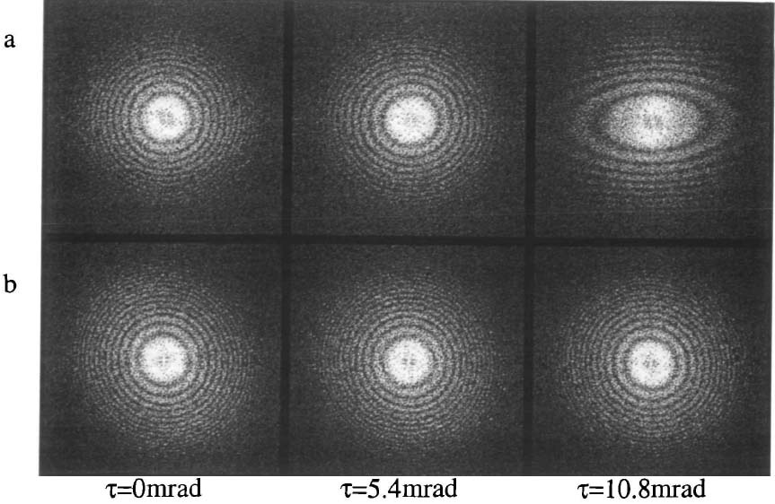
Figure 4329a. Rotationally symmetric magnetic fields and electron lenses. Based on Maxwell’s equation, Laplace’s equation of magnetic potential, ψ(r), can be obtained by, Δψ(r) = 0 -------------------------- [4329b] where the Laplacian Δ is defined in polar (cylindrical) coordinate system by, For cylinder symmetric setups, combining Equations [4329b] and [4329c] one can obtain a solution in the format of a power series, Then, we can obtain, Bz(z) = Br ≈ - 2a1(z)r = -(r/2) ( Therefore, both the scalar magnetic potential (ψ) and the magnetic field (B) depend on the values on the optic axis. By calculating the circular component in Newton’s law equations in combination with Lorentz force, we can obtain that the trajectory for meridional rays in a meridional plane rotating behaves at an angular velocity, This equation is known as the Larmor frequency that is half the cyclotron frequency of an electron on a circular trajectory. Further calculation can help us to find, where, Equation 4329h gives the trajectory r(z) in the meridional plane rotating at the angular velocity ωL. According to Scherzer theorem, the performance of rotationally symmetric electron lenses is rather poor because of spherical (Cs) and chromatic (Cc) aberrations (also called defects). The physical origin for the formation of spherical aberration in the actual magnetic lenses is due to the fact that the electromagnetic potentials satisfy Laplace’s equation in the domain of the electron trajectories. Therefore, the spatial distribution of the index of refraction of electron lenses cannot be formed arbitrarily. Since the potential adopts an extremum at the lenses’ boundaries, the outer (marginal) zones of rotationally symmetric electron lenses always focus the rays more strongly than the inner (paraxial) zones, causing the spherical aberration. Fortunately, Cs can in principle be corrected if at least one of the four conditions in Scherzer theorem has been broken, while in the most successful practices the corrections have been obtained by breaking rotational symmetry. Note that the aberration coefficients C1 and C3 are real numbers and describe rotationally symmetric contributions to the wave aberration. In aberration-corrected EMs (electron microscopes) a combination of hexapole or octupole lenses are used in a aberration corrector which lacks rotational (circular) symmetry and thus doesn’t have to have a positive spherical aberration like conventional, round magnetic lenses. Because the spherical aberration in general is unavoidable for rotationally symmetric electron lenses in EMs (electron microscopes), it can never be aplanatic. However, each electron lens has a coma-free point that locates on the optic axis within the field of the lens. No coma is introduced into the images by any off-axial pencil of the rays whose central ray intersects the coma-free point. In aberration-corrected TEMs, in order to eliminate the off-axial coma, the coma-free point of the lens next to the corrector must match the corresponding point of the corrector field. Later on, Haider et al. [2] corrected the aberrations in TEM imaging mode successfully. Figure 4329b shows an example of diffractogram tableaus of the aligned TEM under both uncorrected and corrected conditions. The figures taken under the uncorrected condition demonstrates that the electron beam tilt about the coma-free pivot point introduces primarily a defocus and an axial twofold astigmatism. The strength of these aberrations does not depend on the azimuthal direction of incident beam due to the rotational symmetry of the aligned TEM. After the aberration correction all diffractograms in the tableau exhibit approximately the same appearance revealing the properties of an aplanatic lens. In this case the illumination tilt does neither introduce defocus nor two-fold astigmatism confirming the correction of spherical aberration.
Figure 4329b. Diffractograms obtained in an aligned microscope without (a) and with (b) correction of the spherical aberration. τ stands for tilt angles.
[2]
In the objective lens of TEM, the magnetic flux generated by the lens coil is condensed at the tip (at the gap) of the rotationally symmetric polepiece, with a bore diameter b and a gap distance S between the poles. The electrons, which travel along the optical axis exactly, do not receive the Lorentz force due to the magnetic field. The incident electrons at a distance r from the axis receive the Lorentz force based on Fleming's left-hand rule, and thus the electron makes a rotational motion.
[1] W. Glaser: Strenge Berechnung magnetischer Linsen der Feldform H =
H0/[1 + (z/a)2]. Z. Phy. 117, 285 (1941).
|
 -------------------------- [4329a]
 ----------------- [4329c]
 ----------------- [4329d]
 --------------------------------- [4329h]
 --------------------------------- [4329i]