Chapter/Index: Introduction | A | B | C | D | E | F | G | H | I | J | K | L | M | N | O | P | Q | R | S | T | U | V | W | X | Y | Z | Appendix
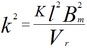
| In the objective lens of TEM, the magnetic flux generated by the lens coil is condensed at the tip (at the gap) of the rotationally symmetric polepiece, with a bore diameter b and a gap distance S between the poles. The electrons, which travel along the optical axis exactly, do not receive the Lorentz force due to the magnetic field. The incident electrons at a distance r from the axis receive the Lorentz force based on Fleming's left-hand rule, and thus the electron makes a rotational motion. The focusing properties of a magnetic lens may be given in terms of a parameter k2, To minimize the aberrations, the objective lens has to be strong. Therefore, Bm must be kept as high as possible but without saturating the soft iron polepieces, while l should be kept small in order to keep the lens compact and the whole microscope column reasonably short. Assuming k2 maintains constant as the accelerating voltage is raised, with Bm fixed, l would have to be increased in proportion to (Vr)1/2. In general, objective pole pieces with small top bore in TEMs have been suggested to have advantages of low spherical and chromatic aberrations and reduced condenser action. TEMs with side-entry specimen stages, shielded objective pole pieces have to be used. However, the objective lenses usually have many sources of lens imperfections such as a relative displacement between upper and lower pole-pieces, and an asymmetric gap between pole-pieces and a yoke. A strong upper-objective polepiece is needed to create a convergent beam to form a CBED (convergent-beam electron diffraction) pattern. For the TEM configuration with a top-entry type EDS detector, the detector is placed above the objective lens in a TEM system with a high viewing angle (e.g. 70 °) to a horizontal specimen. Since the detector takes X-ray signals from the top of the objective lens, a large bore polepiece for the objective lens is needed. The use of such polepieces degrades the spatial resolution as well as the probe size. For TEMs with top-entry specimen stages, in order to insert a tilting holder, the top entry pole piece requires a relatively large upper bore. In some designs, the maximum tilting angle can be about 30°. Furthermore, if the focal length is kept really short to give the highest spatial resolution, then such designs are typically unable to be tilted more then a few degrees without blocking the beam path or interfering with the objective lens. Moreover, incorporation of the tilting mechanisms requires a larger upper pole piece bore which degrades the optical properties of the objective lens. The schematic illustration of JEM-2010F objective lens in Figure 4143 presents the typical objective lens in conventional TEMs. The specimen (for side-entry holder) is located at the center of the polepieces. Thee objective aperture (OA) is placed immediately below the specimen and the high contrast (HC) aperture goes through the lower polepiece.
Figure 4143. Typical objective lens in conventional TEMs. In electron diffraction measurement, if we are measuring the HOLZ rings at large scattering angles (e.g. ≥10°), then we need to use known standard samples to correct the distortion in reciprocal space. At such high angles, the electrons travel close to the polepiece and thus the lens imperfection causes the diffraction distortion. However, aberration correction, e.g. Cs correction, can minimize such distortion.
|
 ---------------------------------------- [4143]