Chapter/Index: Introduction | A | B | C | D | E | F | G | H | I | J | K | L | M | N | O | P | Q | R | S | T | U | V | W | X | Y | Z | Appendix
| The schematic illustration in Figure 4264a presents the position of image-forming lens system in typical (S)TEM systems.
There are two methods normally used for spherical aberration correction at high accelerating voltages in TEM and STEM: i) Using magnetic hexapoles with transfer round lenses [1] in both TEM and STEM system; ii) Combining four magnetic quadrupoles and at least three octupoles in STEM system [2] due to its off-axis aberrations. Image-forming Cs-corrector is also called TEM Cs-corrector. Some examples of aberration corrections in TEM imaging mode are shown in page4109. Figure 4264b shows an example of microscopes with the Cs (spherical aberration)-correctors for both probe-and image-forming systems. The image-forming Cs-corrector is mounted between the objective lens and the intermediate lens, and the probe-forming Cs-corrector is between the condenser lens and the condenser mini-lens. The height of each corrector is 25 cm.
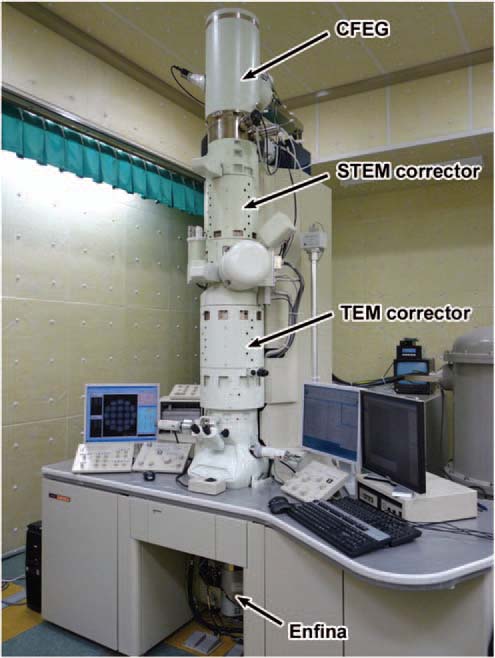
Figure 4264b. JEM-2200FS TEM/STEM with probe-and image-forming Cs-correctors. Adapted from [3]. Figure 4264c shows the photograph of a LVEM (low-voltage electron microscope) with delta Cs correctors operated in the range 30 - 60 kV. The CFEG stands for cold field emission gun installed on the top of the column. The delta correctors for STEM and TEM are integrated for both probe- and image-forming systems. An Enfina spectrometer is installed at the bottom of the column for EELS-based measurements.
Figure 4264c. The photograph of a LVEM with delta Cs correctors operated in the range 30 - 60 kV. [4] Figure 4264d shows the full view of of the practical double-sextupole Cs correctors for STEM and for TEM, respectively. The positions of the correctors with respect to the front and back focal planes for STEM and TEM, respectively, are also indicated.
Figure 4264d. Double-sextupole spherical aberration correctors for: (a) STEM and (b) TEM.
Figure 4264e shows the schematic comparison of Zemlin (diffractogram)-tableau characteristics for the axial aberrations up to third orders. First-order aberration (e.g. defocus and twofold astigmatism, A1) shows the elliptical distortion even without electron beam tilting because the impact of first-order aberrations does not depend on the tilt angle. For the aberrations of higher orders (n≥2), such as second-order axial coma B2, three-fold astigmatism A2, third-order spherical aberration C3 (>0), third-order star aberration S3 and four-fold astigmatism A3, there is no elliptical distortion observable for the un-tilted case. In these cases, only at illumination tilts the characteristic distortion due to the aberrations becomes discernible. Note that the higher-order aberrations have equal symmetries to the ones in Figure 4264e as discussed in page3740.
Figure 4264e. Schematic representation of Zemlin (diffractogram)-tableau characteristics for the axial aberrations up to third order.
[1] Haider, M., Braunshausen, G. and Schwan, E. 1995. Correction of the spherical aberration of a 200 kV TEM
by means of a hexapole-corrector, Optik, 99, 167–179.
|
||||