Dark-field (BF) Imaging in TEM - Practical Electron Microscopy and Database - - An Online Book - |
|||||
| Microanalysis | EM Book http://www.globalsino.com/EM/ | |||||
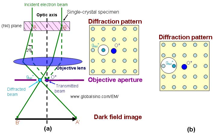
Different from bright-field (BF) TEM imaging condition, in dark-field (DF) TEM imaging condition, as shown in Figure 3354a one or more diffracted electron beams are allowed to pass the objective aperture placed in the back focal plane of the objective lens while the transmitted electron beam is blocked by the aperture. In Figure 3354a (a) a smaller aperture is used to select a single diffracted beam only, while in Figure 3354a (b) a bigger aperture is used to select two diffracted beams. In this case, the specimen is imaged using a parallel incident electron beam(s). Therefore, only a small amount of the electrons that have passed through the specimen are used for imaging. The electrons are diffracted by sets of crystallographic planes, e.g. (hkl) planes in Figure 3354a, and the angle between the transmitted beam and the diffracted beams depends on various crystallographic planes, e.g. 2θB (θB is a Bragg angle). Both the transmitted and diffracted beams are deflected by the objective lens. However, the transmitted beam is delivered to the origin (O*) of the back focal plane, and the diffracted beam to a spot denoted by ghkl*. The inverted bright-field (BF) and dark-field (DF) images are formed by the transmitted and the diffracted beams in the first image plane, respectively.
Figure 3354a. Dark-field (DF) TEM imaging conditions.
The white disks indicate objective apertures.
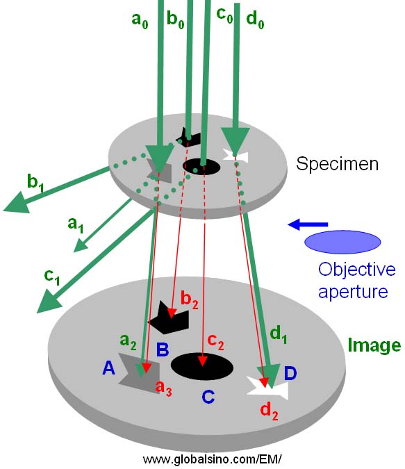
In Figure 3354b, a0, b0, c0, and d0 represent the rays in the incident electron beam, a1, a2, b1, c1, and d1 the rays in diffracted beams, and a3, b2, c2, and d2 the rays in the directly transmitted beam. The direction deviation of the transmitted rays from that of the incident electron beam is due to a magnification caused by the lenses between the specimen and the imaging plane. According to the theory of diffraction contrast formation, in dark field TEM mode, only one or more diffracted beams (a1, a2, b1, c1, and d1) are selected by a proper objective aperture for imaging. Note that the local contrast on the TEM image plane is proportional to the number of electrons striking the viewing screen or detector.
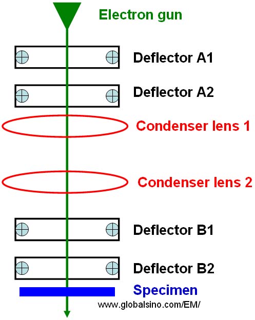
Figure 3354b. Schematic illustration of diffraction contrast formation in TEM imaging mode. Any optical defects, e.g. chromatic and spherical aberrations, affect the performance of the electron microscopes such as the contract of the bright field images and the quality of the dark field images in TEMs. Dark-field images are constructed using electrons scattered at relatively large (≥ 30 mrad for STEM) angles and are dominated by elastic and thermal diffuse scattering. The spatial resolution degrades when a small objective aperture is used to reduce the inelastic scattering contribution to bright field images, or to exclude closely spaced spots to form dark field images. Figure 3354c shows the schematic illustration of deflectors and condenser lenses above the specimen in TEM. The electron gun consists of a filament and a column where the incident electrons are accelerated. The functions of double deflectors A1 and A2 are gun shift and tilt, while the functions of double deflectors B1 and B2 below the condenser lens 2 and above the specimen are beam shift and tilt as well as tilt for dark field imaging. The beam shift and tilt are also called illumination shift and tilt.
Figure 3354c. Schematic illustration of deflectors and condenser lenses above the specimen in TEM. In summary, in practice, there are two different operation methods to achieve DF imaging: Figure 3354d illustrates the comparison of the main contrasts in both CTEM and STEM modes.
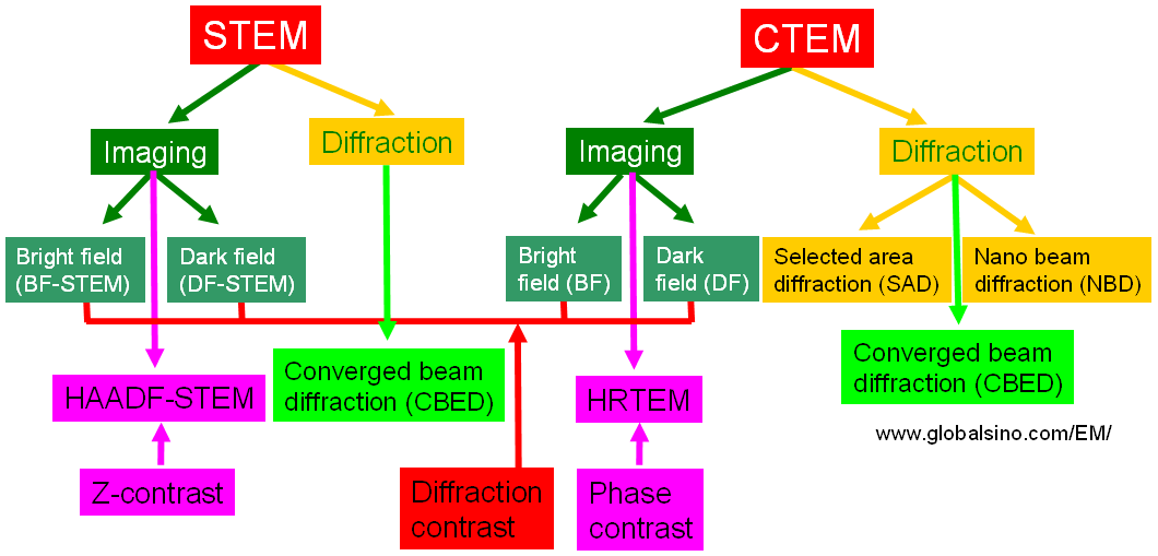
Figure 3354d. Comparison of the main contrasts in both CTEM and STEM modes.
A dislocation can be observed in TEM because the lattice near the dislocation core is bent elastically. The degree of bending increases when closer to the dislocation core. Dark-field imaging mode, also called weak-beam (WB) technique here, is normally used for dislocation imaging. In addition to the applications mentioned above, dark-field TEM imaging is also a classical technique used to map strain variation in crystals when the thickness, composition and crystalline orientation are constant. However, this technique cannot give quantified strain so that a constant strain field, resulting in a uniform contrast, cannot be interpreted. Therefore, such analysis requires accurate theoretical diffraction models.
|
|
||||