=================================================================================
A deflector for electron-beam deflection in EMs has been applied to align, tilt, shift, scan the electron beam, and so on. The deflector, usually including a pair of deflection coils, is called the double-deflection system. The deflectors are used in the following systems:
i) The illumination system.
ii) The electron gun.
iii) The image-forming system.
iv) The projection system.
In the arrangement of the basic imaging systems of conventional transmission electron microscopy (CTEM), an electron beam emitted by a source radiates the TEM specimen, usually through an illuminating system of lenses as shown in blue in Figure 3764a. The incident electrons interact with the specimen and thus are scattered. The electron beam after interaction is then focused by the objective lens, forming an image. The image is further magnified by projector lenses to produce an image at proper magnifications. Note that in modern TEM systems additional lenses, intermediate lenses are also placed between objective lens and projector lenses.
For scanning transmission electron microscopy (STEM), the same diagram can be used with a reversed direction of the electron beam also shown in Figure 3764a. The mini-lens and the deflectors underneath the objective lens are introduced to decrease off-axis astigmatism and field curvature at low magnification. The electron source for STEM replaces the TEM detection system (image plane). In modern STEM systems, a field-emission gun can be used to produce an electron source as small as 10 nm in diameter. One or more projector lenses in TEM (acting as condenser lenses in STEM) with a short focal length demagnify the source to provide the flexibility in the beam parameter. The beam is then demagnified further by the main lens in the systems, which is objective lens to form a small probe of 0.2 – 1 nm on the specimen. Therefore, a STEM probe can be considered as a demagnified image of the source. Note that the focal length of the objective lens can be as small as 1 mm. The scanning coils are deflector coils, built into the bore of the objective lens, and serve to scan the electron probe over the specimen. The detector on the STEM image plane collects the electrons transmitted, or scattered, by the specimen.
Figure 3764a. Schematic illustration of imaging geometries of TEM and STEM systems. The green lines show the common paths of the rays of CTEM and STEM illuminations. The blue arrows indicate the rays for the TEM illumination, while the red arrows indicate the directions of STEM rays. The STEM image is formed on the left-hand side, while the CTEM image is on the right-hand side. The yellow lenses are the common lenses for both STEM and CTEM systems.
Figure 3764b shows the schematic illustration of deflectors and condenser lenses above the specimen in TEM. The electron gun consists of a filament and a column where the incident electrons are accelerated. The functions of double deflectors A1 and A2 are gun shift and tilt, while the functions of double deflectors B1 and B2 below the condenser lens 2 and above the specimen are beam shift and tilt as well as tilt for dark field imaging. The beam shift and tilt are also called illumination shift and tilt.
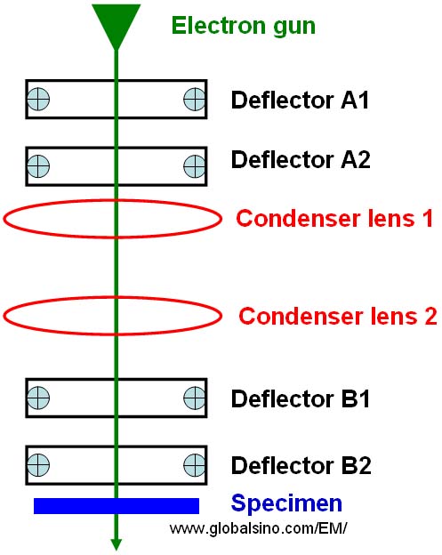
Figure 3764b. Schematic illustration of deflectors and condenser lenses above the specimen in TEM.
In Cs correctors, a number of deflection coils are added in order to match all optic axes of the elements for compensating for small relative misorientation (for instance, of the fields in double hexapole Cs correctors) caused by inaccurately machining.
In many commercial TEMs, both coma-free and voltage-centering alignments use the same beam deflectors above the objective lens for adjusting the direction of incident beam, the coma-free alignment is achievable only at the expense of the voltage-center alignment, and vice versa. However, it was also proposed [1] that the coma-free alignment can be obtained by using beam defectors above the objective lens, while the voltage-centering alignment is adjusted by beam deflectors below the objective lens.
Note that in EMs except for alignment deflectors, stigmators, and multipole aberration correctors, all the other conventional optical lenses are cylinder symmetric.
[1] T. Yanaka. K. Shirota, A. Yonezawa and Y. Arai, in: Proc. 8th Int. Cong. on Electron Microscopy. Canberra. 1974. Vol. I. p. 128.
|