=================================================================================
Based on the theory of wave aberration function and the relationship between the scattering angle and the reciprocal position u at the back focal plane of a lens, we can convert the distance W to a phase shift (also called phase difference) (see Equation 3752a). Therefore, the phase shifts due to the spherical aberration and defocus (as well as defect of focus) can be combined into a single phase factor χ, given by,
 -------------- [3731a.a] -------------- [3731a.a]
 -------------- [3731a.b] -------------- [3731a.b]
In general,
 -------------- [3731b] -------------- [3731b]
where,
Cs -- Spherical aberration coefficient, defining the quality of objective lens,
λ -- Wave-length,
Δf -- Defocus value,
|g| -- Spatial frequency,
C1 = Δf,
α -- The convergence semi-angle.
The first term on the right-hand side in Equation 3731a represents the effect from the spherical aberration while the second term represents that from the defocus of the objective lens.
As indicated in Figure 3731, the spherical aberration from a round lens leads the rays off-axis to be deflected more strongly than for an ideal lens, resulting in a positive phase shift. Based on Equations 3731a, at low convergence semi-angles (α) in STEM, this phase shift caused by the spherical aberration can be partially compensated for the low spatial frequencies by applying a negative defocus, while at high α, this phase shift cannot efficiently be canceled out because the spherical aberration dominates the aberration function χ(α). Scherzer suggested that the maximum aperture size, α0, should be defined by limiting the phase error across the aperture to the values equal to or smaller than a quarter wavelength (i.e. |χ(α)| ≤ π/2) by balancing Δf against Cs. In other words, a maximum acceptable phase shift of π/2 across the objective lens is practically tolerated, allowing a maximum convergence semi-angle α0.
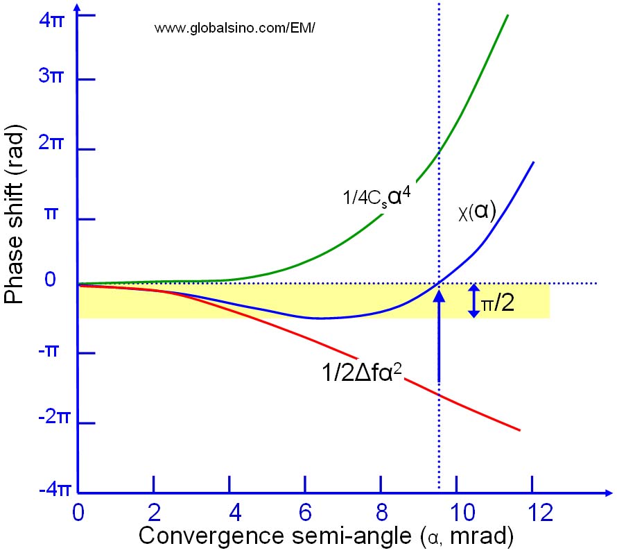
Figure 3731. Compensation of phase shift between spherical aberration and defocus.
Particularly, the effect of spherical aberration can be partially compensated for by applying the Scherzer defocus, which provides a wide bandpass of the same phase contrast.
Based on the optical reciprocity theorem [1], BF-STEM images can be related to the HRTEM images of an atom as a phase object. Like HRTEM images, BF-STEM images are very sensitive to the focal conditions, and contrast reversal is often observed because of multiple scattering and phase shift due to defocus condition of the lens. A full interpretation of BF-STEM images can be done with phase contrast simulation in the same way as the HRTEM images. [2]
[1] Born M, Wolf E. Principles of optics. Cambridge, UK: Cambridge University Press; 1997.
[2] Spence JCH. High resolution electron microscopy. 3rd ed. Oxford: Clarendon Press; 2003.
|